Ferrite Loaded Magnetic Loop Antenna
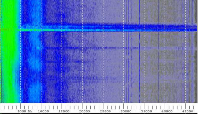
Figure 1: Lightning Strike
Introduction
Of the numerous manifestations of Magnetic Loop Antennas, many of them employ magnetic core. Although the use of wire wound onto ferrite cores of various shapes is common, loading of an antenna with ferrite beads has historically been limited to dipole antennas. [1] Loading a single turn large loop magnetic antenna, of one meter diameter, with appropriate ferrite beads, can create an effective aperture equivalent to 100 turns with any resonance at least ten times higher than the corresponding 100 turn unloaded version.
Additionally, large loop high turns magnetic antennas usually have high electrical resistance due to the high wire gauge imposed by size constraints, which makes the use of current amplifiers unfeasible. A single turn large loop of copper tubing of one meter diameter can have milliOhm resistance, but will exhibit low gain by itself. Loading the single turn copper tube with an appropriate high permeability ferrite can effectively increase the gain, in this case, the equivalent of a 100 turn antenna or 40 db, while retaining its milliOhm resistance and unusually wide bandwidth.
A preamplifier was designed with an effective voltage gain of 500 or 54 db and a 30 kHz bandwidth at -3db. The preamp is placed directly at the output terminals of the loop antenna to minimize noise associated with long transmission lines, which is common practice.
Antenna Specifications
A single loop of copper tubing was cut and loaded with ferrite beads as follows:
Loop diameter = 1.0 m
Copper tube OD = 0.25 inches
Copper tube ID = 0.125 inches
Ferrite Core: TDK H70 T14X3X8
Loop’s Inductance with 1000 core = 288 uH
Loop’s Resistance = 6.8 mOhms
The inductance of the loop was measured with an Agilent U1731A Handheld LCR meter.
The loop resistance was measured with an Extech 380560 Milliohm meter.
The ends of the copper tube can be threaded to accept 0.25 inch nuts for mounting and attaching the preamp enclosure as well as fastening the preamp lead wires. This simplifies mechanical requirements between the preamp enclosure and antenna, rather than trying to solder leads to the copper tube and rigging clamps.
Formulas for the loop inductance are ubiquitous and do not need to be reiterated. The formula I used [2] computes the bare unloaded 1.0 meter copper loop to be roughly 2.85 µH. Loading the copper loop with 1000 ferrite cores and setting Mu to 100 computes to roughly 285 µH. This approximates the LCR meter readings. The ferrite beads increase the loop gain by a factor of 100 or 40 db.
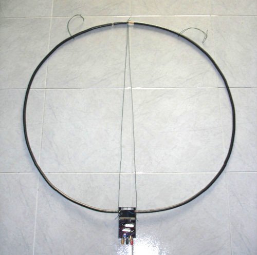
Figure 2: Ferrite Loaded Magnetic Loop Antenna
Preamp
The AD620 instrumentation amplifier used is equivalent to the LT1167. This is an ultra low noise instrumentation amplifier designed for low level sensor signals. The gain of 500 is set by R3 = 100 Ohms. The bandwidth computes to approximately 30 KHz simulated by LTSpice using only an AC voltage source. Replacing the AC voltage source with an equivalent loop antenna model, as shown in the schematic, Figure 3, and setting Mu = 1, for an unloaded antenna, produces the gain frequency response shown in Figure4. Setting Mu = 100, as indicated by the measurements, the gain frequency response is shown plotted in Figure 5.
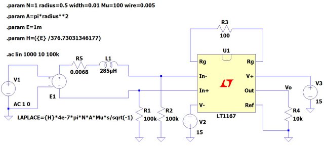
Figure 3: Ultra Low Noise Preamp Schematic
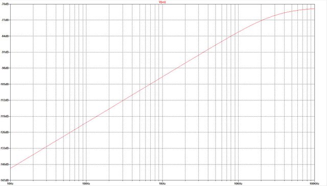
Figure 4: Gain for Antenna Mu = 1, y = -147dB to -70dB, x = 10Hz to 100KHz
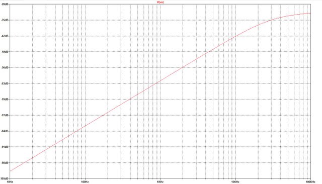
Figure 5: Gain for Antenna Mu = 100, y = -105dB to -28dB, x = 10Hz to 100KHz
The circuit was hand wired on a perf-board and mounted in a plastic box along with two 9V batteries, Figure 6. The circuit does have a pair of electrolytic capacitors and a pair of ceramic capacitors bypassing the batteries. There are three banana jack connectors showing on the bottom of the box so that power can be supplied, if the batteries are not installed. The voltages can range from +/- 9V to +/- 15V.
The PCB must be carefully cleaned to remove any contaminates and solder flux to avoid abnormal behavior of the precision instrumentation amplifier. Careful attachment of the wires from the circuit board to the antenna is necessary to prevent spurious signals arising from vibration and loose connections, particularly to the copper tubing.
The circuit board should have a proper ground plane and be mounted inside a metal enclosure, not a plastic box, which helps to eliminate electronic noise and spurious signals.
Inserting the entire antenna into a large ID copper tube and grounding one end can act as an electrostatic shield. Wrapping the entire length with copper tape and grounding one side is an alternative. This is similar to using transmission line cable as a magnetic antenna and breaking the shield conductor to avoid creating a shorted turn which shorts out the incoming signal. An electrostatic shield was not implemented here and good results were obtained despite that.
It should be noted that this is a balanced loop antenna feed into the preamp. Care should be exercised to avoid inadvertent grounding either side of the antenna copper tube or the feed wires.
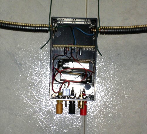
Figure 6: Preamp Cennected to Antenna
Results
The signal was fed into the “Line In” of the available computer audio ports and selected as input in “Spectrum Lab” audio options. [3] Spectrum Lab was started with the preamp turned off. The resulting spectrum is shown in Figure 7. The no signal noise floor spectrum is -120 db.
The preamp power switch was turned on. The noise floor immediately moved up to around -70 db as shown in Figure 8. This clearly shows a voltage gain of over 500. The magnetic loop antenna under test was in the laboratory. No effort was made to remove the antenna to a quiet magnetic environment.
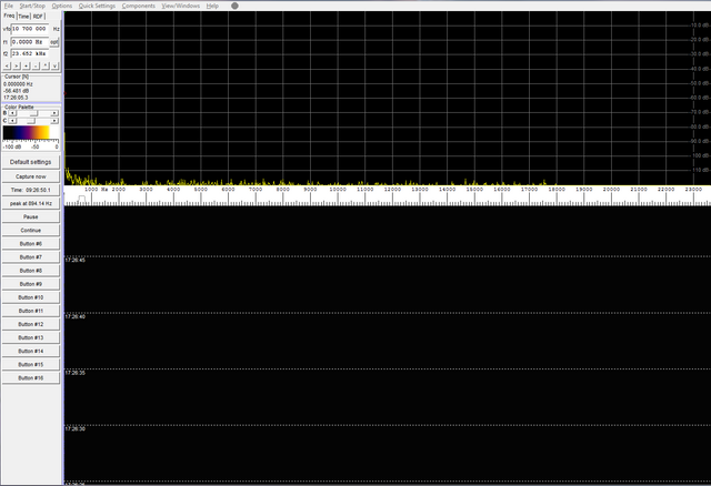
Figure 7: Preamp Turned Off, y = -120 db to 0 db, x = 10 Hz to 24 KHz
It was observed that USB audio devices, such as webcams with microphones, can interfere with audio capture in Spectrum Lab. A webcam was disconnected which resulted in an ID out of range error. It was introducing audio it picked up into the spectrum. It was impossible to mute this audio path. This problem was fixed by removing the webcam, its driver and associated applications. Then, the machine was restarted without any USB audio drivers being loaded. This fixed the problem. Also, transmission lines connected to an unused audio stereo port can introduce huge amounts of extraneous noise into the spectrum. I disconnected all webcams and extraneous audio cables and transmission lines to get these results.
Clearly, an anechoic chamber with magnetic shielding would have been ideal for testing. But, the building is steel reinforced concrete that acts like a Faraday shield for most of the RF spectrum, including cell phones. I have to pipe 4G signals through a bulkhead in the window to have any cell phone reception inside. This applies to the entire RF spectrum. All of my antennas must be on the outside of the building to have any decent reception. However, this architecture apparently does not appreciably attenuate the magnetic spectrum.
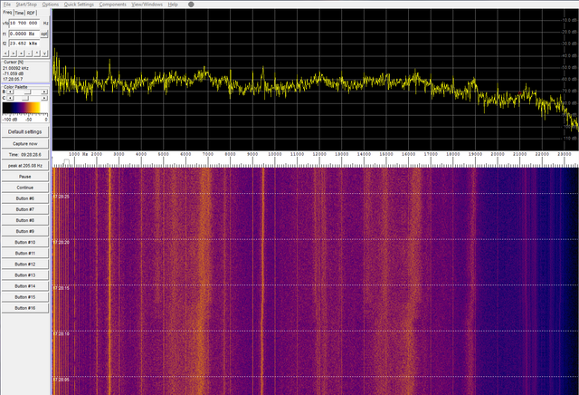
Figure 8: Preamp Turned On, y = -120 db to 0 db, x = 10 Hz to 24 KHz
To verify that this antenna preamp combination was working and could receive a magnetic signal, I used a UHF magnetic TV loop antenna to inductively couple a signal to it. A 50 Ohm resistor was inserted between this UHF loop and a signal generator. A 2 volt peak to peak signal was injected into the UHF loop antenna at 10 KHz. The signal can clearly be seen at 10 KHz in the spectrum shown in Figure 9. A sharp line at 10 KHz is observed in the waterfall.
It also appears that part of the spectrum roll off around 24 KHz is not the instrumentation amplifier, but the 24 bit audio A/D converter in the PC audio circuit. The only way around this is to obtain a much higher bit rate audio A/D converter card and insert it into one of the PC slots.
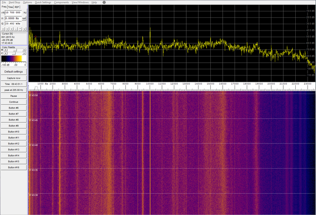
Figure 9: Inductive Coupled 10 KHz Signal, y = -120 db to 0 db, x = 10 Hz to 24 KHz
Conclusion
A single loop 1 meter diameter magnetic loop antenna for ELF/SLF/ULF/VLF frequencies was constructed from a copper tube. That tube was loaded with 1000 ferrite beads which produced the equivalent of a 100 turn magnetic loop antenna. The ferrite beads have an initial permeability of 1500. The effective distributed air gap of the ferrite bead construction yielded an effective permeabiltiy of 100. A preamp was constructed with a voltage gain of 500 and attached directly to the loop antenna leads. The entire assembly exhibited a broad bandwidth of 24 KHz, which was limited by the PC audio A/D converter. The noise floor across the bandwidth was -70 db and started to fall off around 20 KHz.
References
[1] DeMaw, M.F., “Ferromagnetic-Core Design and Application Handbook”, Prentice-Hall, Inc., 1981, page 113.
[2] https://technick.net/tools/inductance-calculator/circular-loop/