Designing a Linear Bearing
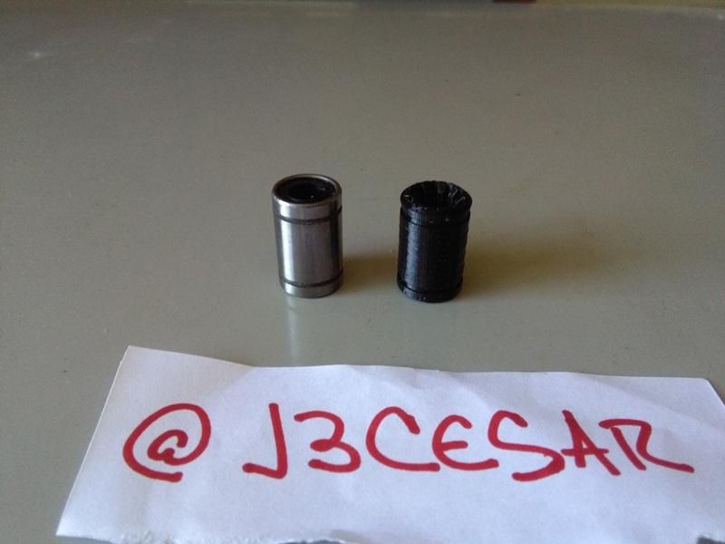
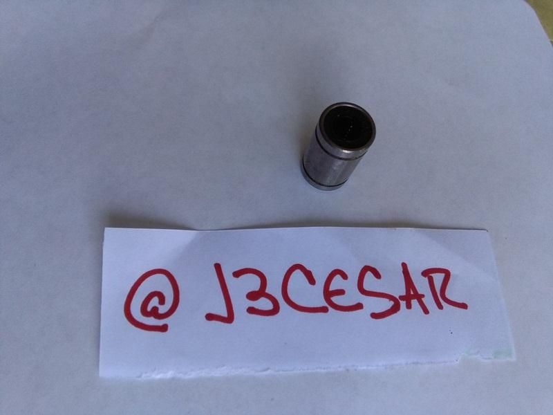
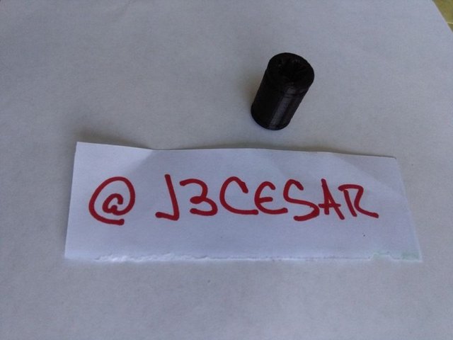
hi friends, today I come with a new delivery on a design in Autodesk inventor, then create the piece in the 3D printer. The model below is based on a LM8UU linear bearing that is commonly used in 3D printers and CNC machines.


The first thing is to establish the sketch to generate the external radii and according to the dimensions to create the extrusion of the piece.

The extrusion will be about 3 millimeters in order to generate a surface with notches in order to place a retainer. This is achieved with sketches superimposed on each extrusion expanding or decreasing the diameter to be extruded as the case may be.


Next we create an extrusion but with the difference that it will be of subtraction of volume, in order to generate the shape of the internal hole of the bearing lm8uu.

At this point I will teach you a new technique, which is the chamfer, which would be like a straight edge around a circumference. We go to the 2D model section and choose the chauffeur option, then click on the edge of a radius and set the millimeters of the chamfer, press accept and ready.

We draw the internal channels that will serve as a system of displacement in the smooth bar of 8mm and we carry out an extrusion of subtraction of volume.


Finally created our model of Lm8uu does not have disadvantages with respect to the original model, since functionally we obtain the same performance, adjustment and quality in linear displacement in the chromed bar of 8mm. I have already made about 12 to have them as spare XD


I hope you liked this post and you can comment to leave your suggestions or requests to digitize specific pieces.