What I Love Doing, My Profession: How To Make A Voltage Doubler
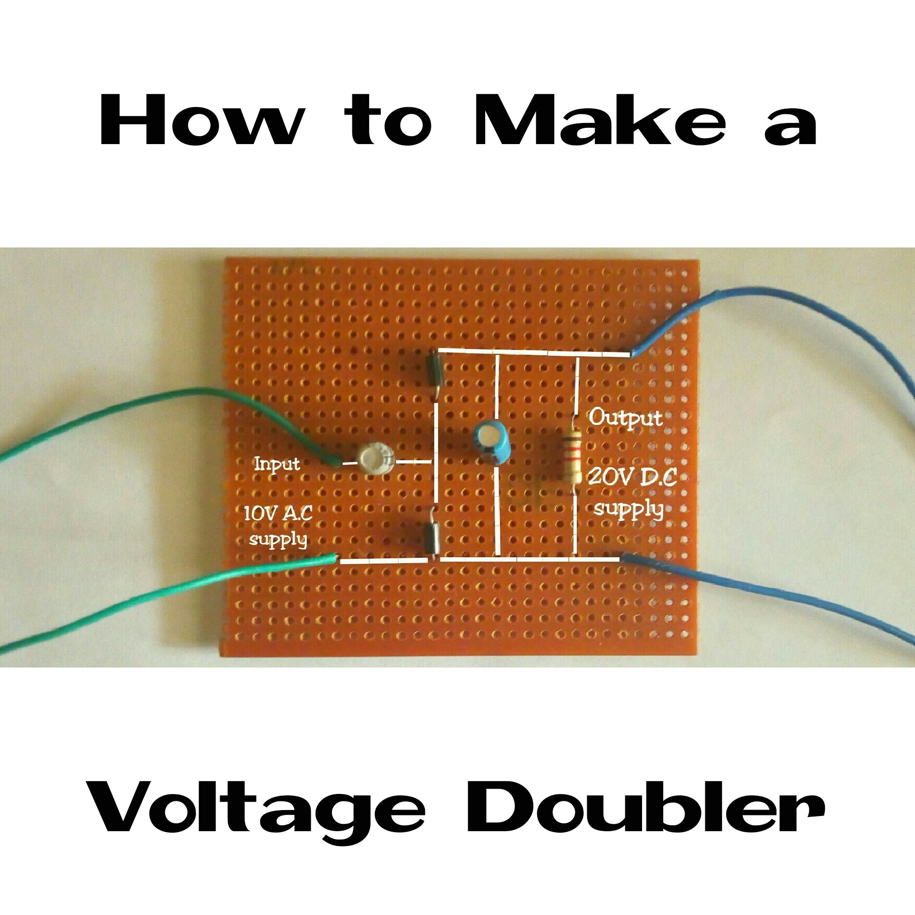
Hello steemians, today I will be sharing with you how a voltage doubler is being made. This is my first practical exercises in Electrical/Electronic Maintenance and Repairs. I was to build a voltage doubler. The circuit diagram was given to me by the lecturer. It a 10volts A.C.(Alternating Current) doubler circuit to 20volts D.C(Direct Current)
What the lecturer was trying to achieve was "Testing our soldering skills". Although I'm not yet perfect using the soldering iron but I have always put it into practice and I'm getting better.
We were already informed about the practical exercises earlier on before that day so we could get our electronic components and the material needed ready; which I already got mine.
The Tools and Components used.
• Soldering Iron
• Soldering Lead
• Vero Board
• Hand Cutter
• Some wires
• Two(2) 10uF, 25V Capacitor(polarized)
• Two(2) IN4001 Diode
• One(1) 1kilo-ohms Resistor
How the connection was been made:
• Two Diodes are connected in series.
• The positive terminal of one Capacitor is connected to the cathode of the Diode and the negative to the anode of the Diode in parallel.
• One Resistor is connected in parallel to the Diodes in series and Capacitor in parallel.
• The negative terminal of the other capacitor is then connected in parallel to the node where the diodes are connected in series.
• The positive terminal of the capacitor connected in parallel to the Diode node is taken as one of the input terminal and the anode of the diode is taken as the other input terminal.
• The output terminals then taken from the Capacitor and Resistor connected in parallel with the Diodes.
How the soldering was been carried out:
• Firstly, arrange the components on the smooth surface of the ferro board according to the circuit diagram.
• Secondly, turn the ferro board over and solder the leads of the components to the shiny part of ferro board.
• Thirdly, use the soldering lead to link each terminals across each other.
• Lastly, solder a wire at the input and output terminals.
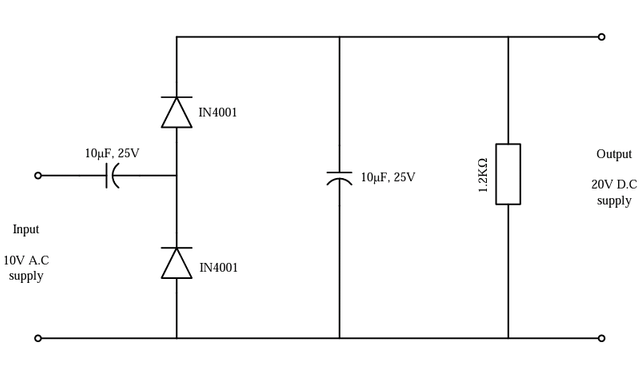
Circuit diagram
Drawn with Microsoft Visio by me

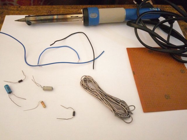
Tools and components used

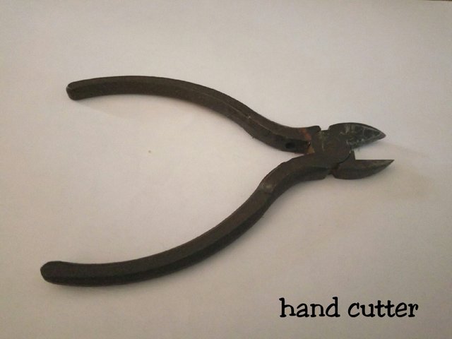
Hand Cutter: used to cut the excessive leads of the components so as to obtain a neat soldering.

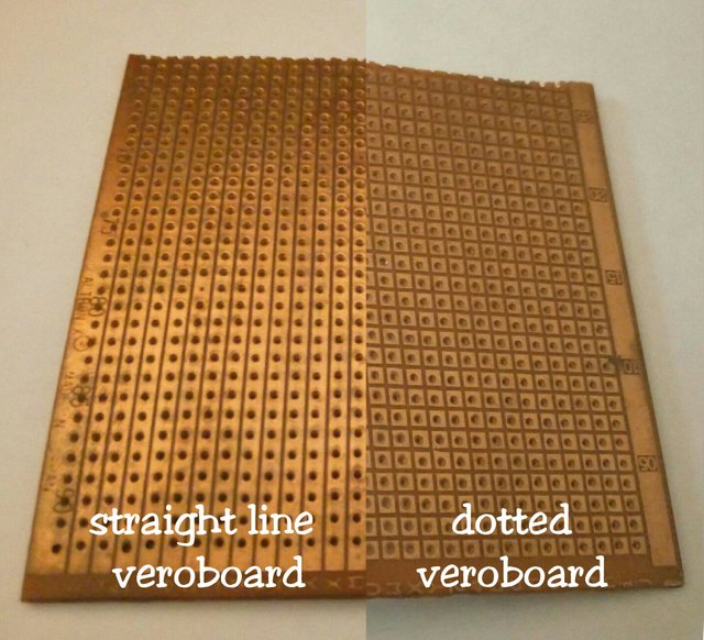
The two types of Veroboard which are;
i. Straight line Veroboard
ii. Dotted Veroboard

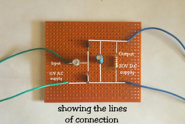

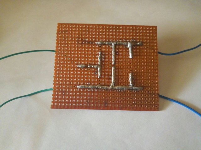
Soldering print beneath the veroboard

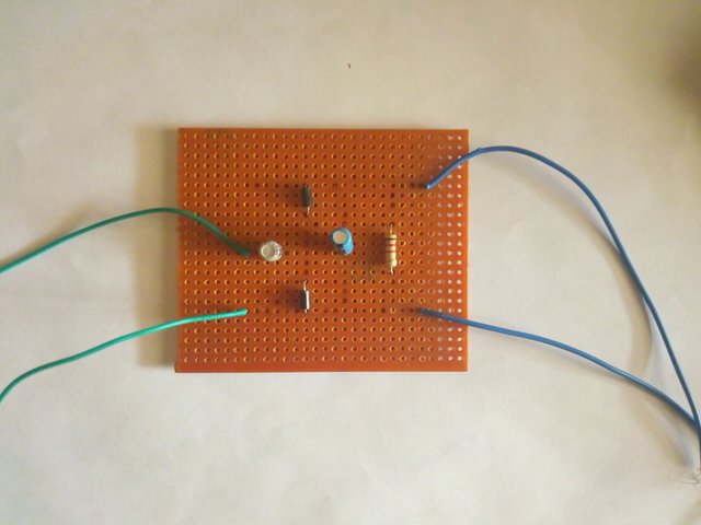
A completed voltage doubler circuit.


It so easy!
Indeed! It is
And in your country are sold veroboards models of other types?
No, just those two types.
Congratulations @k-banti! You have completed some achievement on Steemit and have been rewarded with new badge(s) :
Click on any badge to view your own Board of Honor on SteemitBoard.
For more information about SteemitBoard, click here
If you no longer want to receive notifications, reply to this comment with the word
STOPCongratulations @k-banti, this post is the third most rewarded post (based on pending payouts) in the last 12 hours written by a Dust account holder (accounts that hold between 0 and 0.01 Mega Vests). The total number of posts by Dust account holders during this period was 18613 and the total pending payments to posts in this category was $6514.34. To see the full list of highest paid posts across all accounts categories, click here.
If you do not wish to receive these messages in future, please reply stop to this comment.
Awesome post my man. It is great to see you have this kind of passion ;) Keep up the good work! Blessings
Thanks so much.