SLC22/WK1: Advanced Electrical Transformers and the Power Factor
Hi friends, we are back again in the SLC for the first week of the twenty-second season. Welcome to my blog as we glance through the lesson of the day. Let's begin...
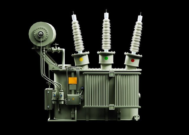 Source Source |
|---|
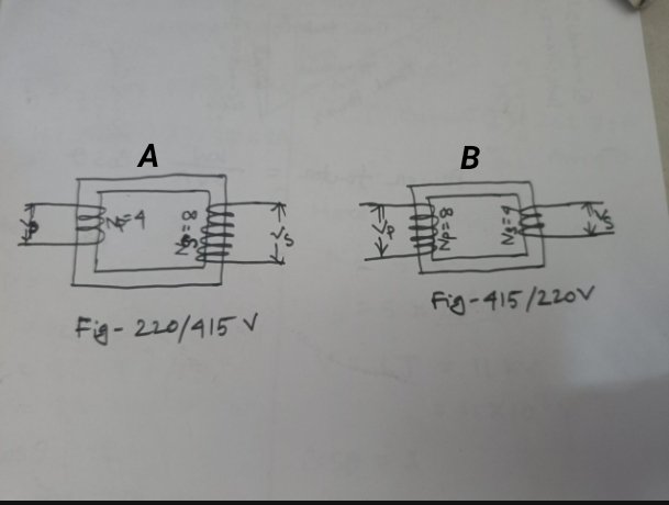 Copied Copied |
|---|
Name of Transformers
A — Step-Up Transformer
B — Step-Down Transformer
Why
A — A Step-Up Transformer, as we know, converts low voltage to high voltage for further transmission. From the above diagram A, we can see the voltage conversion of "220/415V"; this implies that the transformer is stepping up from 220V to 415V. This is typically the function or characteristic of a Step-Up Transformer therefore, figure A is a Step-Up Transformer.
B — A Step-Down Transformer, on the other hand, converts high voltage to low for final consumption. Diagram B above shows a voltage conversion of "415/220V", indicating that the transformer is stepping down from 415V to 220V. This is a typical function or characteristic of a Step-Down Transformer therefore, figure B is a Step-Down Transformer.
Turn Ratio
Since the turn ratio of a transformer can be calculated in three ways, here I will be using the Voltage Ratio for calculating the turn ratio.
Transformer A: Step-Up Transformer - Turn Ratio
Voltage is 220/415
Ep = 220V
Es = 415V
a = ?
Where Ep is the primary voltage, Es is the secondary voltage, and a is the turn ratio.
Since a = Ep/Es
a = 220/415
a = 0.53
Transformer B: Step-Down Transformer - Turn Ratio
Ep = 415V
Es = 220V
a = ?
Since a = Ep/Es
a = 415/220
a = ~1.9
 SourceEdited SourceEdited |
|---|
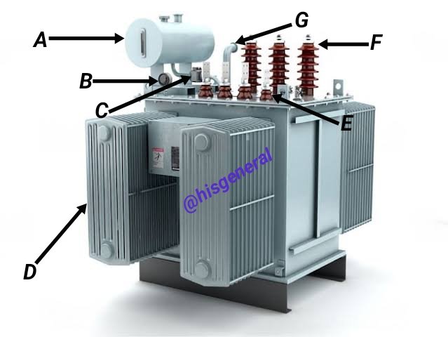
A - Conservator:
This is the part in which oil is stored which allows it to expand and contract alongside temperature changes.
B - Temperature Gauge:
This is another part or component of the transformer for monitoring the winding temperature, oil, or ambient air for overheating detection.
C - Buchholz Relay:
This is a device or a component of the transformer that carries out fault detection, such as insulation failure, oil leakage, or overheating, and, in the course of any of the faults, triggers an alarm or trips the circuit breaker.
D - Radiator:
This component of the transformer drives away heat that is generated by the transformer while on load, making use of fins or tubes to raise surface area.
E - LT Bushing:
The LT (Low Tension) bushing, being the secondary part of the transformer, is used for insulating and connecting the low-voltage winding to the output (load) circuit.
F - HT Bushing:
The HT (High Tension) bushing, being the primary side of the transformer, is for insulating, connecting, and inputting high voltage to the high-voltage winding of the input circuit of the transformer.
G - Breather:
This is a part of the transformer that allows the entrance and exit of air in and out the [ank of the transformer while maintaining moisture out, keeping internal pressure as well as preventing degradation of oil.
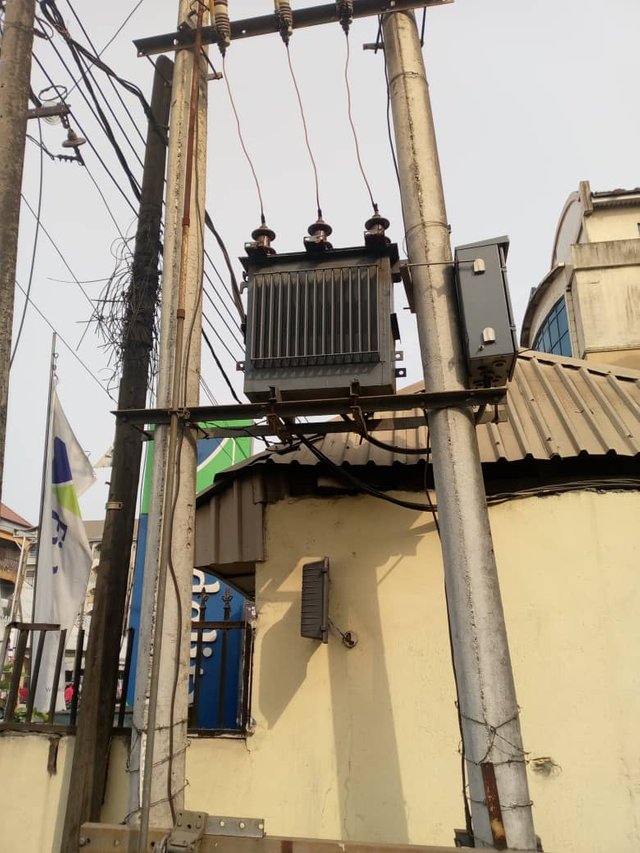
This is the transformer used for my home's electricity, and from every indication, it is a 3-phase, step-down transformer as it is for domestic use. From the picture, we can see the HT bushing, the primary side of the transformer for input, is properly connected. Since there is a power supply, the LT bushing, the secondary part of the transformer for output to load, is equally properly conned, though not visible from the photo.
One thing I cannot really explain here is why this transformer of ours does not have a conservator, Buchholz Relay, and temperature gauge. Whether the transformer type does not have these components or any other reason is quite beyond my understanding and explanation.
However, though these components are not present on this transformer, we still have our normal power supply anytime it is given and that is the confusing part of it.
To calculate the KVA of a transformer for a load of 5000KW, we will have to convert 5000KW to KVA, this will help ascertain the equivalent of it in KVA. To do this conversion, we divide the load (KW) by the power factor (PF which is 0.9 and somewhat a constant), thus:
KVA = ?
KW = 5000
PF = 0.9
Therefore,
KVA = KW/PF
KVA = 5000/0.9
= 5555.56~5555.6 KVA or 5556 KVA
This means that a transformer of 5556 KVA will be required for a load of 5000KW
 Copied Copied |
|---|
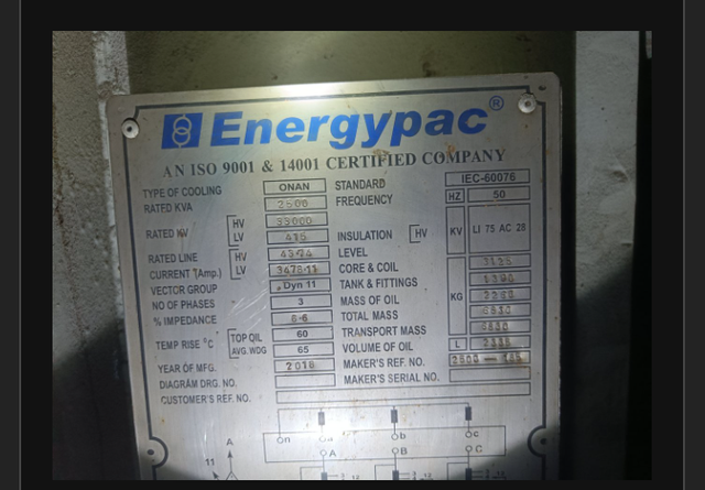
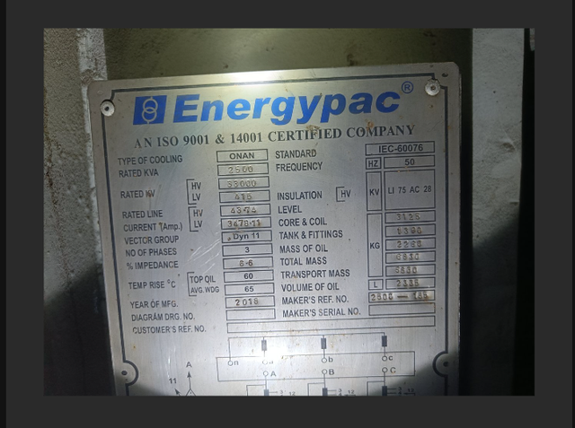
Transformer Name: Energypac
Transformer Rating = 2500 KVA
Primary Voltage(HV) = 33000 KV
Secondary Voltage (LV) = 415 KV
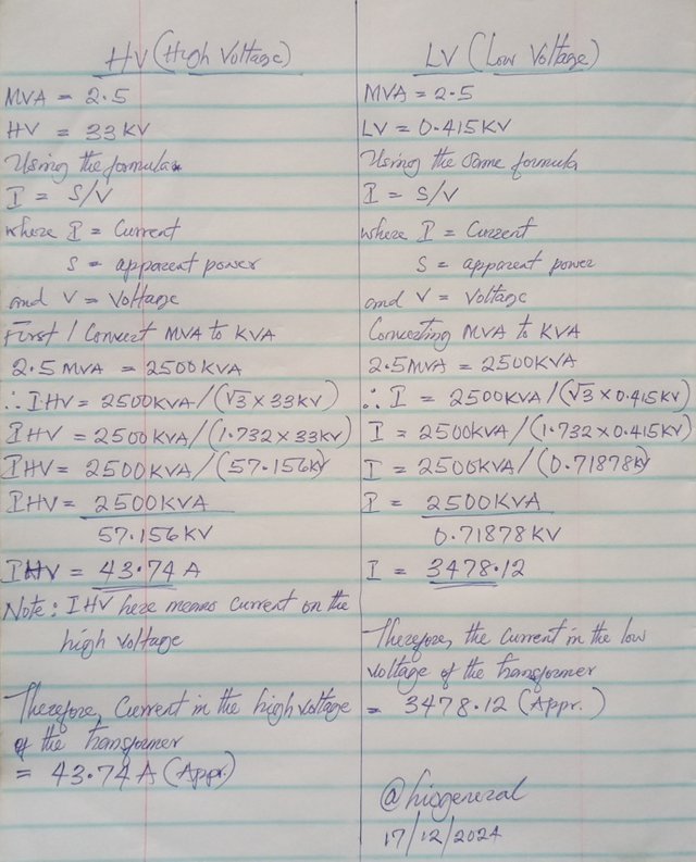
Current(HV) = 43.74 Amp
Current(LV) = 3478.11 Amp
Power Factor (PF) refers to the ratio of the active or real power, which is measured in watts (W), to the apparent, which is measured in volt-amperes. Power Factor is the measure of how efficiently the current generated and derived from the grid is transformed to noteful work.
Power Factor (PF) is calculated by dividing the real power(W) by the apparent power (VA), thus
PF = W / VA
A unity power factor, i.e., 1, shows that all drawn current is transformed into useful work, without the component of reactive power. A power factor less than 1 shows that most of the current isn't performing any beneficial work; rather, it is instead generating reactive power.
There is variation in the value of recommended or required power factor by electricity supply companies based on country and region. In numerous countries, what is recommended is a power factor of 0.9 or higher to reduce the loss of energy.
A high power factor portrays effective utilization of electrical power, whilst on the contrary a low power factor shows wasted power.
A power factor survey conducted at many Nigerian electricity supply companies indicates an average power factor (PF) of 0.78.
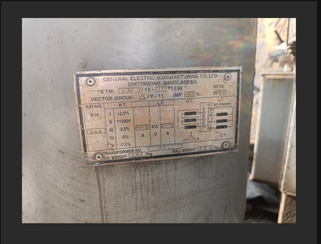
Three differences between A and B
| Points of Differences | A | B |
|---|---|---|
| Impedance | 6.6% | 4.01% |
| Oil weight | 2260 kg | 244 kg |
| Rating | 2,500 KVA | 200 KVA |
Determine True/False:
The name of the oil used in a transformer is pyranol. True
The core loss of the transformer is in the winding. False
The efficiency of the transformer is less than that of other electrical devices. True
The transformer rating is in KW. False
The transformer's insulation test is done with a megger meter. True
X promotion link