Digital Design: Practice with Enconder by @juanjo09
Introduction
I have never posted in this community, but its content has seemed very attractive; and I think this post will have more appreciation in this community.
I made this post based on my project yesterday (I designed a code converter) I want to show you this, because many people are unaware of what they use on a daily basis. the intention is that many have an idea of how a computer, a telephone or a calculator is designed and have a notion of what is inside those "electronic roaches" that make everything work.
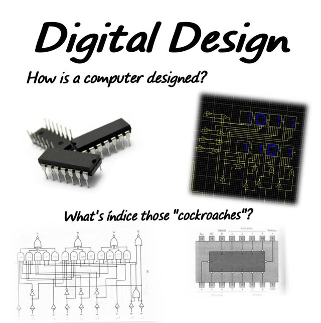
Looking for what to design
I am an electronics student. A branch with great application today is digital electronics, unfortunately my university is unemployed (there are no academic activities until further notice), so I decided to be self-taught and perfect my knowledge in this area on my own. for this I opened a very good book.
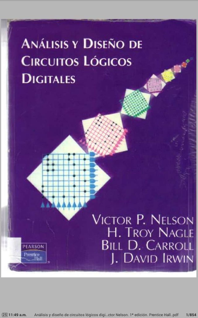 Screenshot of the book I use, you can download the book for free here and in Spanish here
I downloaded this book several years ago on the elsolucionario.org page.
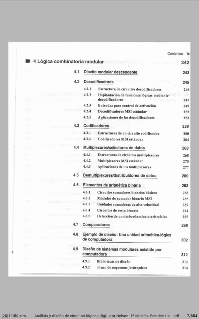
I checked the table of contents and went directly to the exercises in Chapter 4 (I only went through those topics where I felt weak)
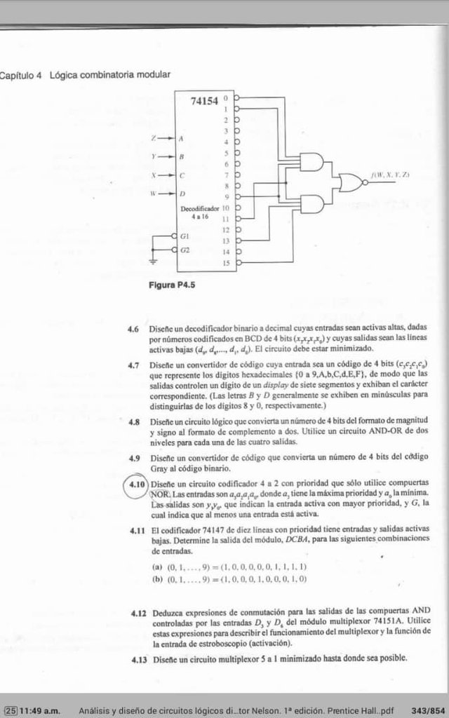
When I went to the exercises section I decided to do exercise 4.9, well, I did not know what the Gray code was, so it seemed good to know it with an exercise, however, as the exercise seemed very simple, I decided to modify it and put it a little more Difficult for me, I decided to make the system show on a display the conversion of a gray, decimal and binary code controlled by buttons just like a computer keyboard.
Design process
In order not to omit both technicalities, I upload a sheet with the competent analytical process to set up the exercise (truth table, between design of gates)
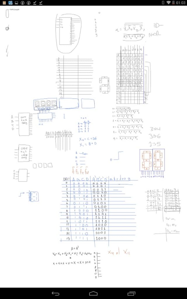 screenshot of my computer
Once the competent calculations were done, I started to mount it on a circuit simulator for android (for me it is one of the best, for now) called DroidTesla (it can be downloaded at googleplay here )

Screenshot
It took me about 4 hours to assemble the circuit, I used OR and NOT gates in addition to the 7-segments and when I finished it was like this
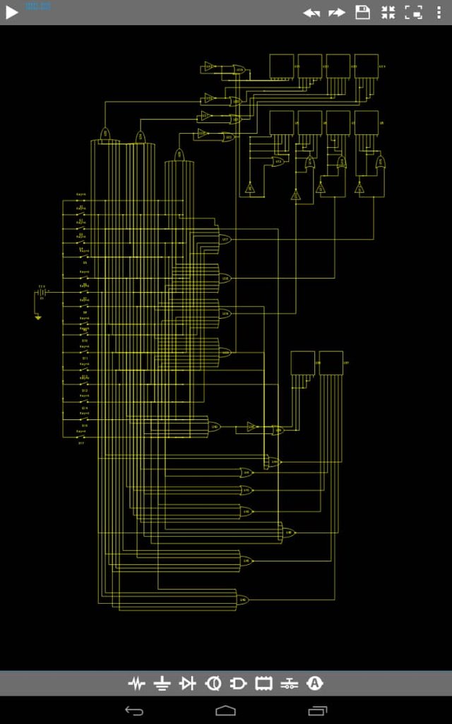
I know it looks like a spider web haha but it is actually the logical circuit to achieve the code converter, I will explain it briefly
How does it work?
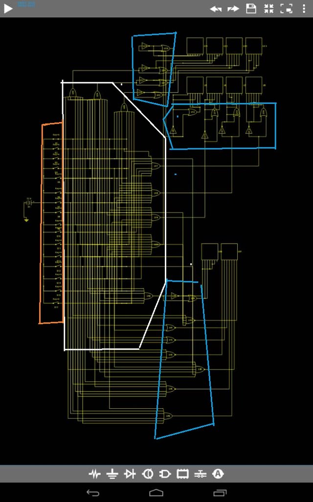
We can divide it by section, where what is enclosed in an orange polygon is the control section (the keyboard) where the first one is 0 and the last one is 15. The white polygon encloses the coding stage structured by OR gates where it enters 16 signals and Only 8 signals are output and the blue polygon circuits are logic circuits that prepare the coded signal and show it on the display
when running the circuit, we then observe:
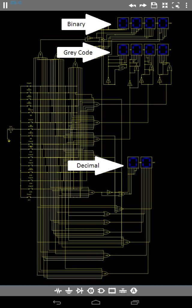
then it works as follows. We select a button, this is in order from 0 to 15 so that if we press the fifth button it will give us the number 4 and it will show its decimal value, Gray code and Binary code on the respective displays.
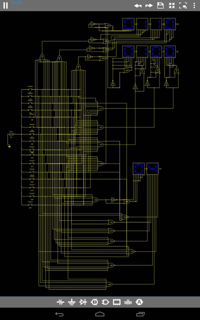 example with the number 4
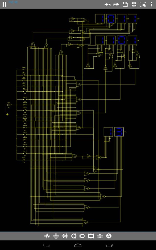 example with the number 13
Last words
And this was my technological project yesterday. I hope you found it interesting and can understand a little more how digital systems work.
perhaps some still do not understand what all this is. what you saw in this post is a digital system from scratch, the lot of connections and "gates" is what is inside an IC (integrated circuit).
In real life this would be part of a computer circuit, for example. I plan to continue uploading very diverse posts like this one, about technology and art