S19-Wk4: Data-sheet for NPN and PNP Transistor Measurements
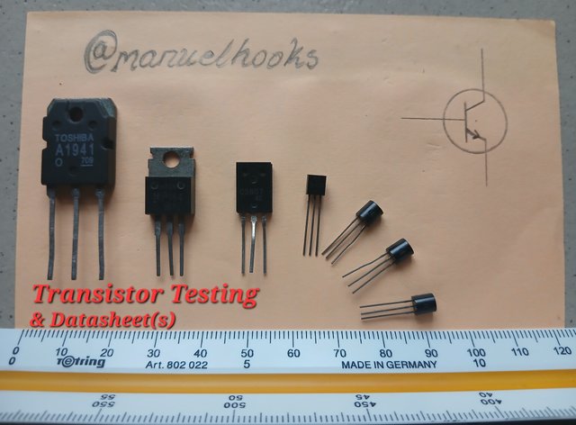 Captured and edited With Galaxy-A15
Datasheet for NPN and PNP Transistor Measurements
Workshop [Task 1]
Datasheet and diagram
Datasheets are a kind of documentation made available by manufacturers which contains detailed information about a specific electronic component.
In this case, a transistor.
The datasheet provides the transistor's features, application, description, and operating information.
Irfz24A
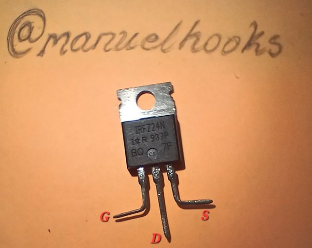 I got an IRFZ24N...[Captured with Micro function on Galaxy-A15]
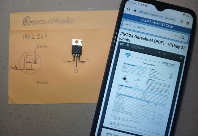 Diagram of an IRFZ 24a Mosfet transistors with Datasheet
| This is a link for an Irfz24A datasheet you can also download Irfz24A Datasheet in PDF format for more comprehensive details. |
|---|
Observation.
Initially, this transistor will only read when the red probe is at the Drain, and the black probe is at the Source. Reversing the probes position between these two will not produce any deflection of the needle.
But if while the red probe is at the Source, and the black probe is at the Drain, and you don't have a reading. Maitain the position of red Probe at the Source, take the black to the Gate, and when coming back to the Drain, it gives a small reading.
Note that you will only get this if you start the test by bridging both the Gate, Source, and Drain together...
N5551
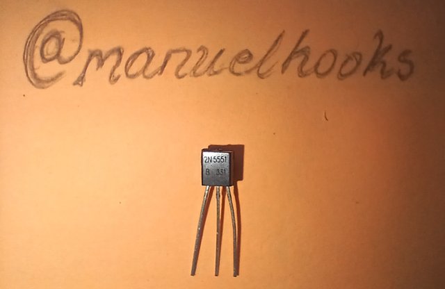
I got a 2N5551...[Captured with Micro function on Galaxy-A15]
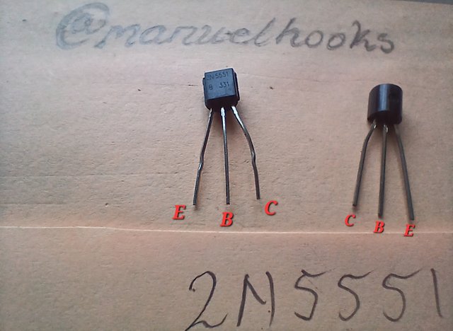 when facing Up amd when facing down
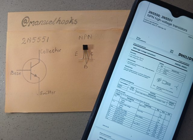 Diagram of a 2N5551 PN-junction transistors with Datasheet
| This is a link for an 2N5551 datasheet you can also download 2N5551 Datasheet in PDF format for more comprehensive details. |
|---|
Observation.
The Analogue Multimeter reads when the black probe is at the base reading with the red at the emiter and at the collector. Any other connection did not produce any difflection on the needle.
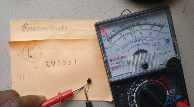
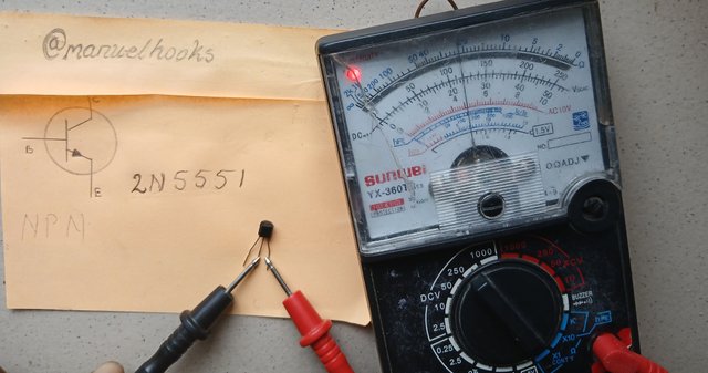
Differences between Irfz24A and N5551
| Particulars | Irfz24A | N5551 |
|---|---|---|
| Package type | To-220AB | TO-220 |
| Switching speed | High | Low |
| Application | High Power | low Power |
| Power dissipation | 150W | 100W |
Workshop [Task 2]
Datasheet
MJE 13003
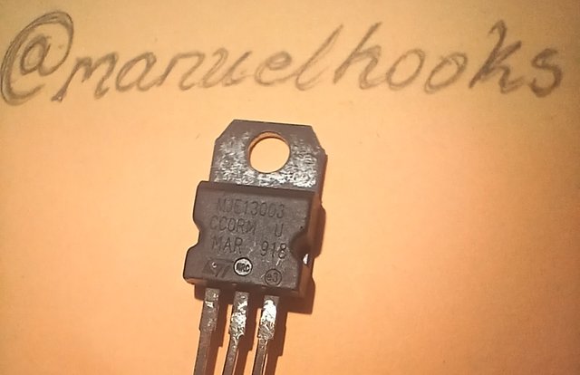 I got an MJE13003 ...[Captured with Mocro function on Galaxy-A15]
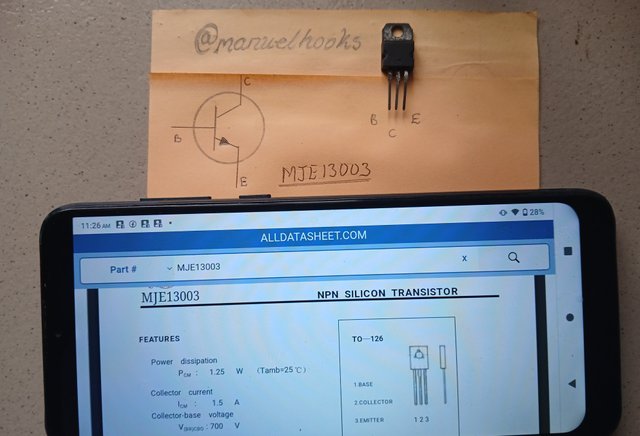
| Here is a link for an MJE 13003 datasheet you can also download MJE13003 Datasheet in PDF format for more comprehensive details. |
|---|
Observation.
As indicated in the picture below, the MJE13003 reads like a true NPN transistor with no complications at all.
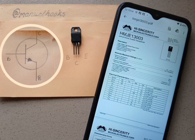 MJE 13003 transistor with Datasheet
PHE 13003C
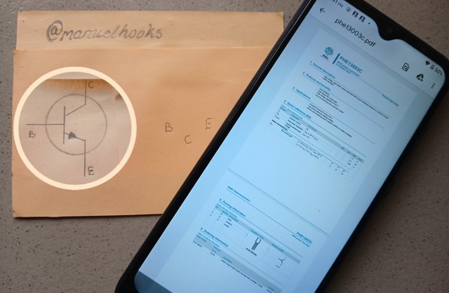
PHE 13003C transistor with Datasheet
| Here is a link for an PHE 13003C datasheet you can also download PHE 13003C Datasheet in PDF format for more comprehensive details. |
|---|
Observation.
The PHE 13003C transistor teads like a true NPN transistor with its base on one side followed by collector and Emitter.
Tip41
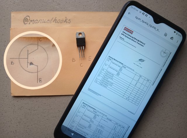
Tip41 transistor with Datasheet
| Here is a link for an Tip41 datasheet you can also download Tip41 Datasheet in PDF format for more comprehensive details. |
|---|
Observation.
The Tip41 transistor reads like a true NPN transistor. When looking at its label, the base is at the left, followed by the collector in the middle and Emitter at the right.
Which is a better substitute?
All three are general purpose transistors in the NPN category. They are all having the same form factor, which is the TO-220 package.
| Particulars | MJE13003 | PHE13003C | Tip41 |
|---|---|---|---|
| Ic at Collector | 4A | 4A | 6A |
| Vceo | 400v | 400v | 100v |
| Vcbo | 500v | 550v | 100v |
| hef | 100-250 | 100-300 | 30-100 |
| Pd | 20w | 20w | 65w |
The PHE 13003C and MJE 13003 have a lot in common and will make a good replacement.
The Tip41 will fit in but not as good as the PHE 13003C and MJE 13003.
The PHE 13003C and MJE 13003 are good for high voltage applications, while Tip41 is good for high current applications.
Testing a PNP type transistor
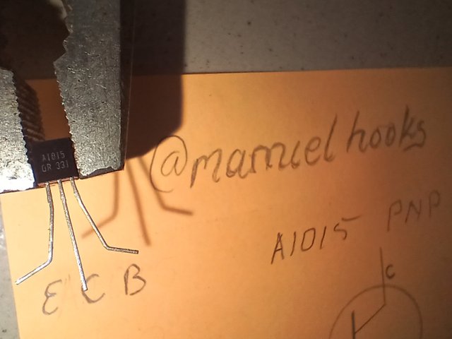
Identify the transistor as PNP from the Datasheet
[Step 1]
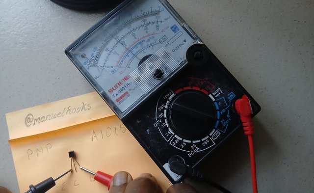
With the red probe at the Base and black on the Emitter, we have a reading
[Step 2]
The red maintains its position at the Base, while the black is moved to the Collector, and we have a reading.
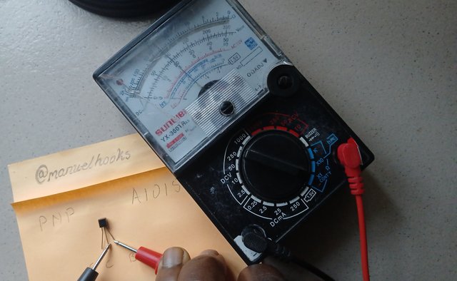
Anithing else will not produce a reading
Just for a confirmation, connecting the Emitter and collector
[Step 3]
Confirmation test: connecting to the Emitter and Collector, then reversing the connection: no reading.
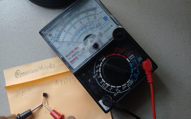
Below is a GIF showing the 3 testing steps conducted on a PNP transistor, starting with the Red probe at the base, and the black probe moving from the collector to the Emitter with their corresponding meter readings.
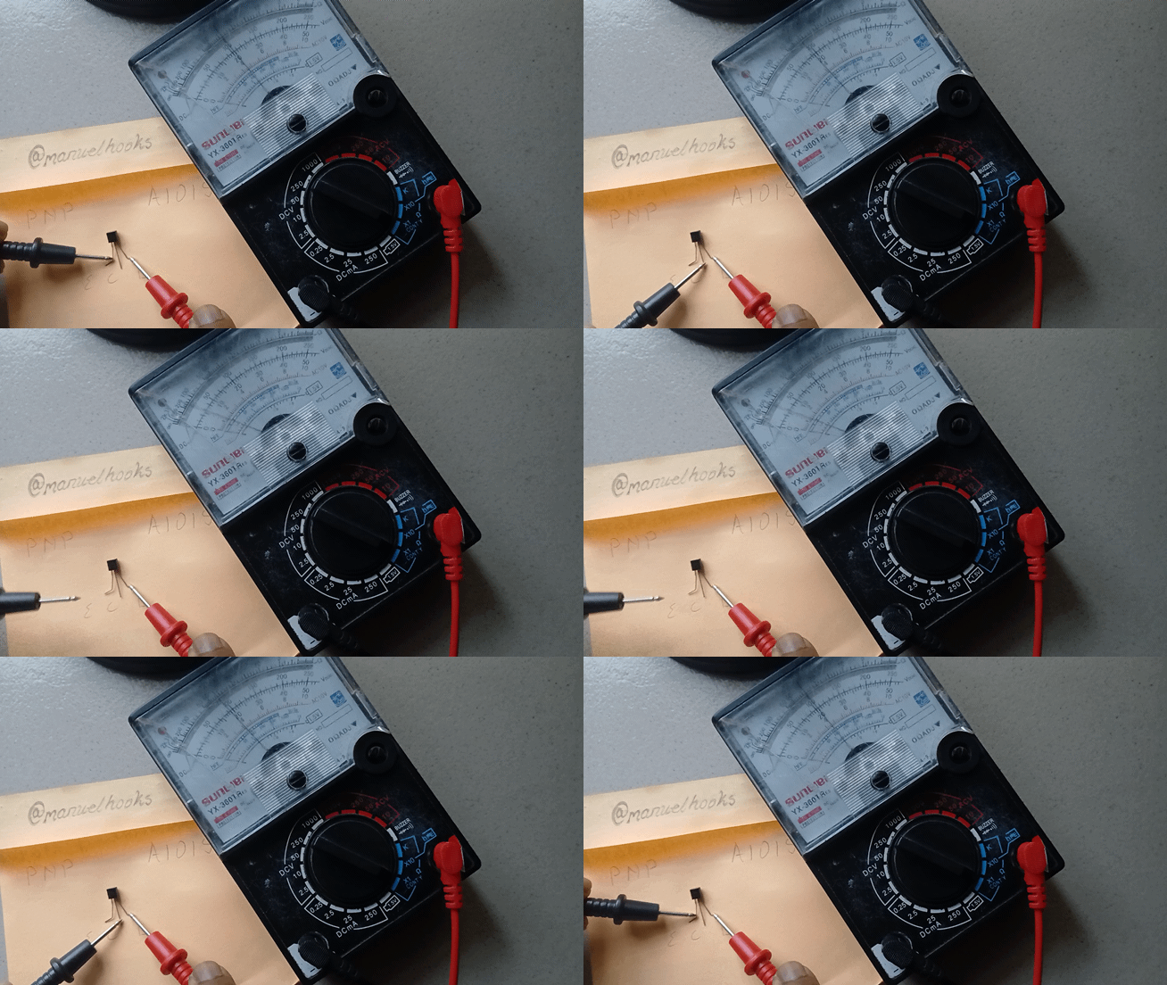
Observation
This A1015 PNP transistor is in good working order.
Testing an NPN type transistor
Step1
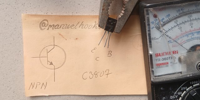
Connect the black probe to the base of the NPN transistor and the red to the Collector.
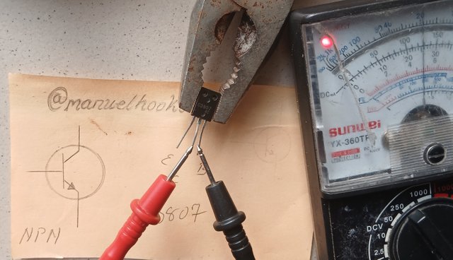
Base and Collector
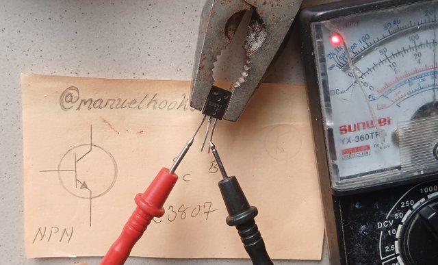
Base and Emitter
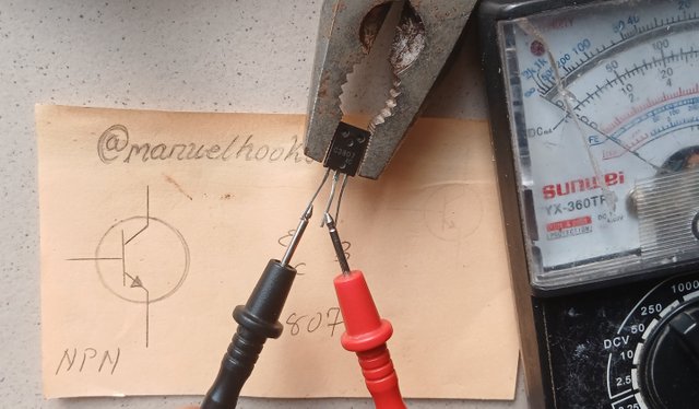
Emitter and Collector
Below is a GIF showing all the 3 testing steps conducted on a NPN transistor, starting with the black probe at the base, and the red probe moving from the collector to the Emitter with their corresponding meter readings.
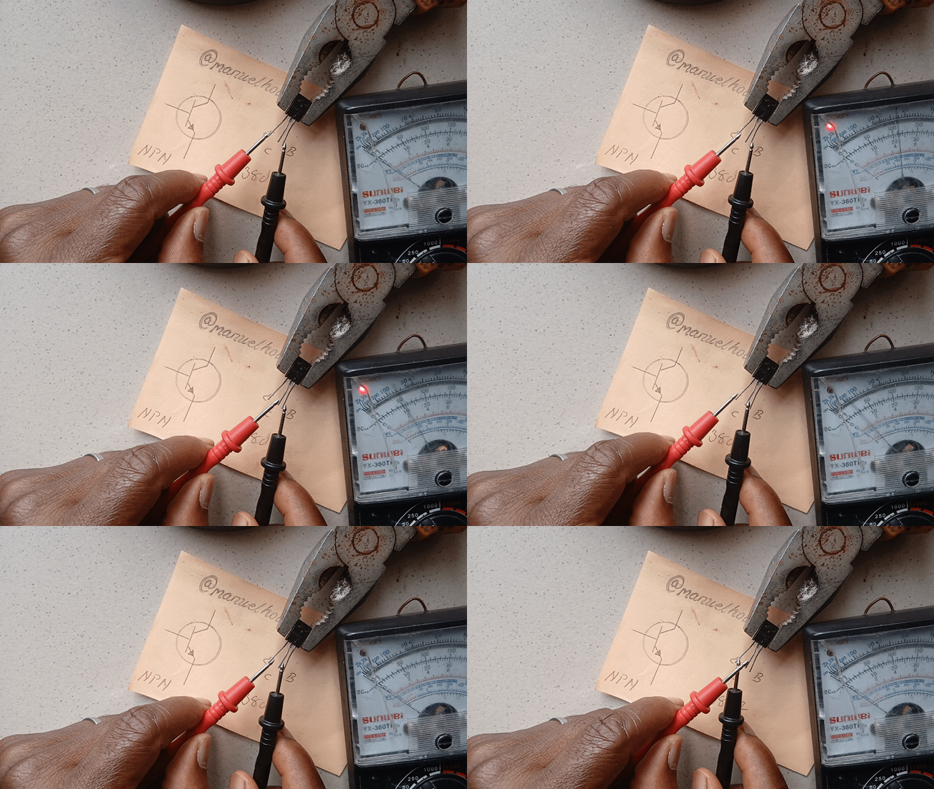
Observation
This C3807 NPN transistor is in good working order.
Conclusion:
This was another interesting exercise with transistors. I now have a better understanding of the Irfz24 transistor and its test procedures. With a better adjusted understanding of the working of an analogue multimeter when testing transistors. I have also figured out how to create and use a GIF to add value to my post.
Invitation to contest
I am inviting @bossj23, @jozzie90, @josepha and @oasiskp
#electronicss19w4 #steemexclusive #nigeria #burnsteem25 #learnwithsteem
#electronics #club5050
Upvoted. Thank You for sending some of your rewards to @null. It will make Steem stronger.
@manuelhooks
Check your tag and the instructions!
Good job keep it up
This is interesting, I don't have a Metre to test my component oo