Modeling a part in Fusion 360, slicing with Simplify3D, and printing on a Lulzbot TAZ 3D printer
This is a tutorial on desktop 3D printing for all you folks that want to 3D print stuff but feel overwhelmed by everything you don’t know about the nitty gritty of it all. I’m striving for a detailed, yet easy to understand step-by-step guide; there will be only three sections: modeling, slicing (file preparation), and printing. I’d like to think that if your luddite uncle read this, they might say “Yeah, I could probably 3D print something -- if I didn’t already know it would result in the downfall of civilization.”
My knowledge and experience comes from being the lead writer for 3DPrinter.net for a couple years and then running my own 3D printing business for several years. I’ve worked with many printers and modeling and slicing programs.
Modeling
The biggest mental hurdle to 3D printing is probably modeling, but it’s much easier than is commonly believed. Sure, there are plenty of 3D libraries such as Thingiverse that enable you to print many objects without ever modeling, but that’s like buying a gaming computer to play Pong. Learning to model is an empowering endeavor that comes with secondary benefits, like a better understanding of manufacturing, dimensions, and the relationship between volume, cost, and functionality.
There are two major styles of modeling objects for 3D printing: sculpting and solid modeling. Sculpting is generally used for creating organic shapes such as people and creatures, and solid modeling is better for mechanical parts, though there is some overlap in their abilities. This tutorial will focus on solid modeling because it’s a bit more practical for getting the most out of a 3D printer, and also because I’m terrible at sculpting.
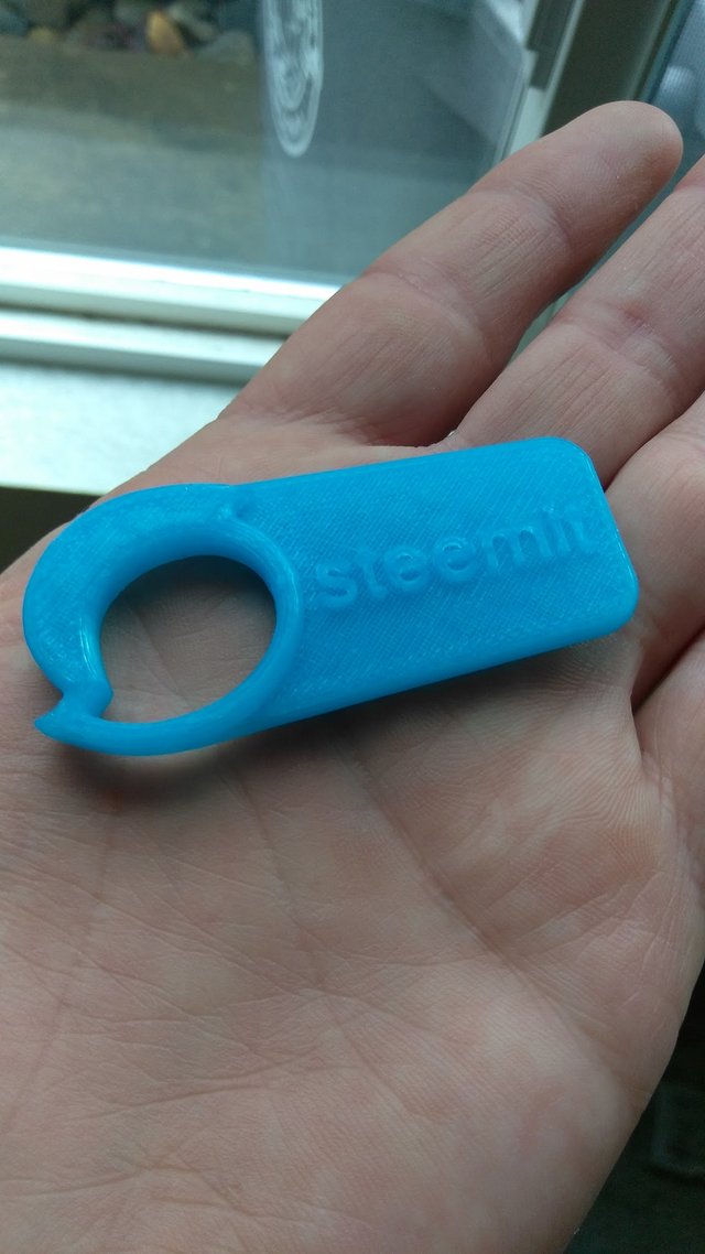
The industry standard for solid modeling software is Solidworks, but it’s stupid expensive, so we’ll be using Autodesk Fusion360, which is amazingly robust for its low price of free (for students and startups). We’ll be modeling the steemit keychain shown above, which has just enough features to demonstrate the basics of modeling.
Solid modeling is so named because all objects begin and end as “solid,” where depth is achieved by extruding a drawn silhouette, and then further shaping involves cutting and more extruding. It’s similar to whittling a toy from a block of wood, only with modeling you get to control the size and shape of the starting block, and you can add more block later. Perhaps it’s not much like whittling.
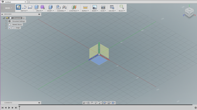
After installing and launching Fusion, we begin by creating a new sketch, which will prompt you to select a plane; any plane will do.

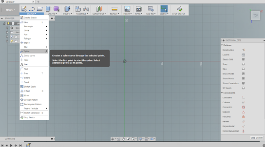
We then use the spline tool to draw the outline of the steemit logo. The spline tool is used for creating custom curves by placing points one after another by clicking. There are tools for drawing squares, circles, curves, polygons, and of course straight lines, but we don’t need to use those yet.
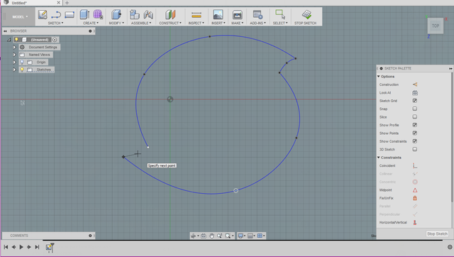
It’s possible to create this shape with only one spline, but sharp angles are better achieved by ending the spline and beginning another; I used two long splines for the main arcs and two short splines to join them. A spline can be made up of as many points as you’d like, but I try to use as few as possible because it’s then much easier to adjust the spline later (I used four points on my long arcs). A point and its curve length/directionality can be adjusted by clicking it and moving it or its handles. They’re pretty intuitive after you play with them for a few minutes.
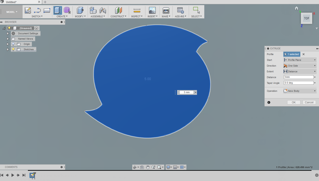
After we have an outline, we give it thickness (“solidness”) by clicking Extrude from the Create dropdown menu, then clicking inside the outline to select it, and then typing 5mm into the Distance box.
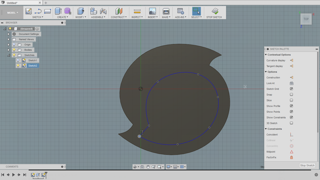
Next, we complete the logo by doing a cut extrusion through the part, starting from the face of the object we just created. So select the top face, start a new sketch, and use the spline tool again to draw the shape. Then click Extrude and type -5mm into the distance box; this automatically changes the Operation to Cut.
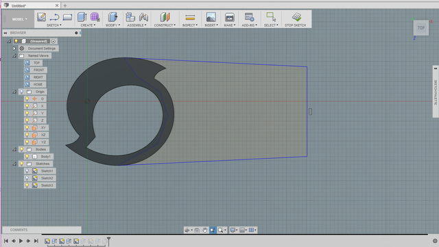
Now we need to add the rest of the keychain by starting another sketch on the plane where we began. The line tool works well for creating this basic shape. After it’s drawn, we’ll Extrude it up 3mm by setting the Operation to Join.
To add the text, we’ll start a new sketch on the newly created face and select the text tool from the Create dropdown, type steemit in the box, and set the size, font, position, and orientation.
Then we’ll extrude this up 1mm.

The only thing left is to round off the edges for a better look and feel. Select the Fillet tool from the Modify dropdown, click the two corner edges, then type 2mm into the radius box.
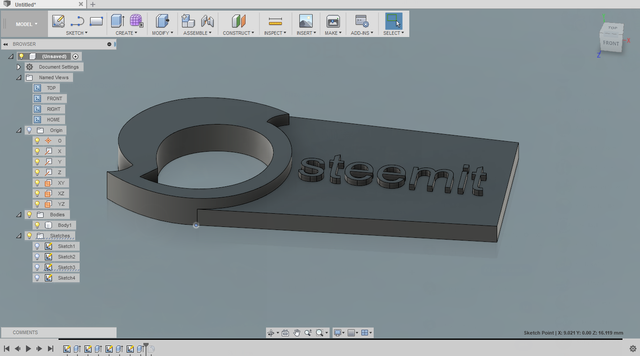
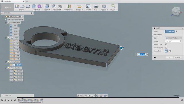
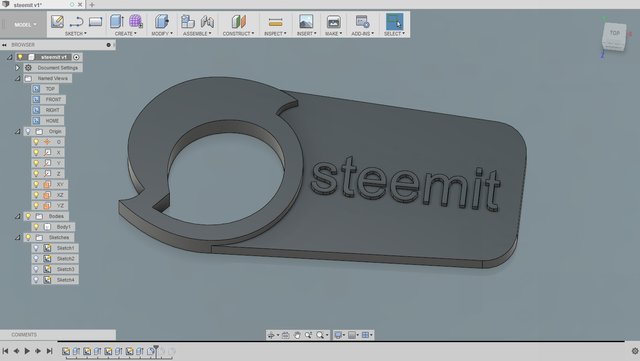
It will then look like this:
Use the Fillet tool again with a 1mm radius on the remaining edges.
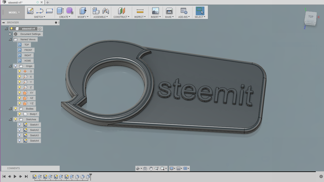
Behold, a 3D model! See, that wasn’t so hard, was it? We now save/export the model as an STL file to send to our slicing software. Do this by clicking File, 3D print, and then selecting the object before pressing enter.
Slicing
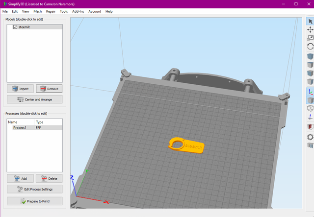
Slicing software prepares 3D models into a format that printers can handle, and they essentially “slice” the models into stacked cross-sections that are printed sequentially from bottom to top, one paper-thin layer at a time. Some printers come with their own slicing software and usually they are lacking in control; their printing options might be limited to “draft” and “high quality” rather than allowing users to set specific parameters. There are a few third-party slicing software options, and the most popular are Cura, which is free and wonderful, and Simplify3D, which is not free but worth every penny according to everyone who tries it, including me. Now we import the steemit.stl file into Simplify3D.
Clicking the Edit Process Settings button opens this window:
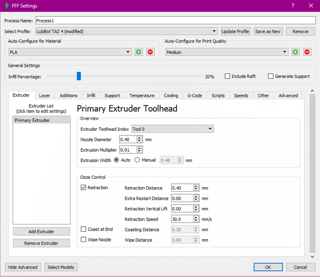
Extruder tab:
The first tab controls extruder selection and parameters relating to filament flow; the extruder is the part of the toolhead that pushes the filament into the hotend and out through the nozzle.
Nozzle Diameter is simply the size of the hole where the filament comes out, and this number can only be adjusted by changing nozzles.
The Extrusion Multiplier determines how much filament is pushed out; ABS requires a multiplier of 1, but PLA usually requires between 0.9 and 0.95. I prefer PLA for its low temp requirements and lower warp attributes, making it generally easier to print with.
Extrusion Width sets how close each line should be drawn to the previous line. Because the plastic stream expands a bit after coming out of the nozzle, it ends up slightly wider than the actual nozzle diameter.
Retraction settings prevent molten plastic from oozing out when the extruder is not printing (while moving to another point) by pulling back on the filament a bit.
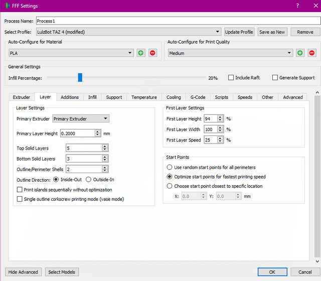
Layer tab:
Layer Height sets the thickness of each layer; we’re using 0.2mm (or 200 microns), which is a mid-high quality setting.
Solid Layers refers to the number of layers on the top and bottom that are printed solid; five 0.2mm layers would be a thickness of 1mm.
Outline/Perimeter shells determines the thickness of walls; two 0.48mm wide walls (from the first tab) will be ~ .96mm thick.
The First Layer Settings allow you to squish and slow down the first layer for better adhesion and definition; many problems with prints are related to poor first-layer quality.
The Start Points options relate to where the extrusion for each layer begins; if all layers begin at the same point, a seam may be visible from the start/stop of the line/perimeter.
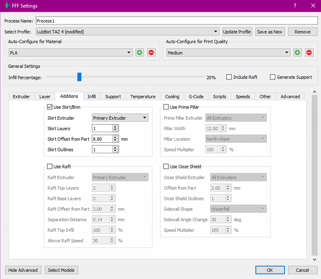
Additions tab:
Skirt/Brim primes the extruder and helps with keeping a part with low first-layer surface area on the print bed by expanding its footprint with extra perimeters. I don’t need a skirt because our keychain is flat on the back with plenty of surface area, so I’ll offset a single brim on the first layer just to get the extruder flowing properly before the actual print starts (because brims always print first ).
Rafts are also helpful with uneven parts as they create a mesh for the part to sit on; we don’t need that for our print.
The Prime Pillar and Ooze Shields are helpful with dual-extrusion prints by keeping each extruder primed as well as printing a wall around the print that catches much of the ooze that’s coming out of the idle extruder. We don’t currently need these.
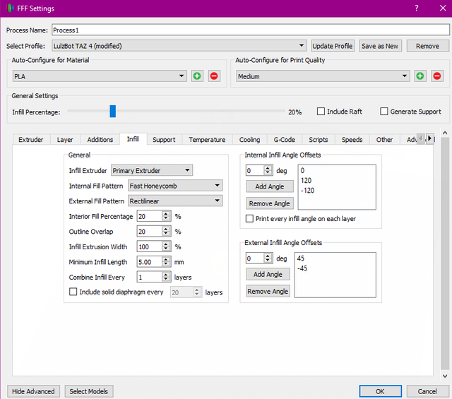
Infill tab:
Internal Infill Pattern can be rectilinear, grid, triangle, wiggle, fast and full honeycomb, or customized through adding angles manually. They all have their pros and cons, but most people seem to prefer honeycomb for its strength and appearance. I like bees and honey so it’s an easy choice for me.
Interior Fill Percentage is how much of the internal volume will be filled, with 0% being a completely hollow part and 100% being totally solid. Generally, a solid part is unnecessary and wasteful because infill of 20-30% provides strength that is nearly equivalent to that of a solid part.
Exterior Fill Pattern affects how the solid top and bottom layers are drawn, either rectilinear or concentric.
Outline Overlap sets how much contact there is between the perimeters and the infill; this rarely needs to be adjusted.
Extrusion Infill Width can be adjusted to increase strength and printing speeds, but we’re not going to do that.
A solid layer can also be added at specified intervals for more strength.
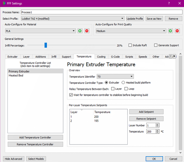
Temperature tab:
The temperature for both the extruder and bed can be set by layer. Usually the first layer is printed a few degrees hotter to improve adhesion. ABS prints with an extrusion temperature of 220-230 degrees Celsius and a bed temp of 90-110; PLA temps are 180-210 and 50-60, respectively, though a heated bed isn’t required for PLA.
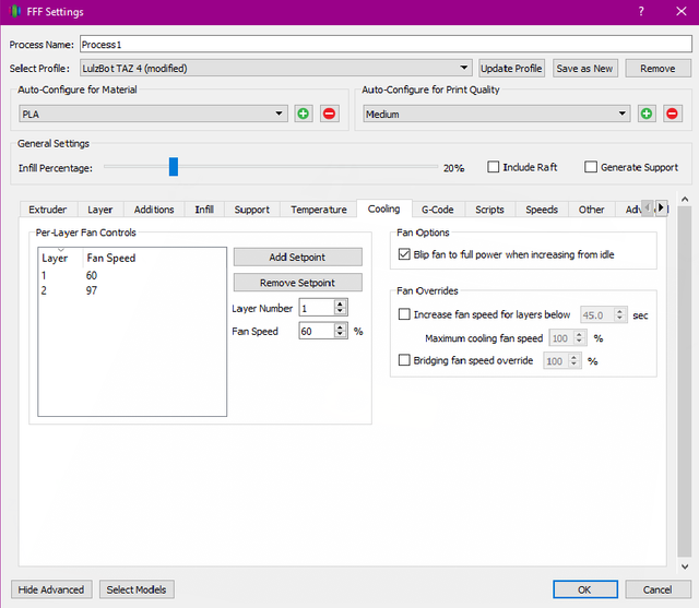
Cooling tab:
The quality of PLA prints and most other materials is drastically improved with a fan that blows directly on the part. ABS prints will warp with the same settings, and most people don’t use a fan for ABS.
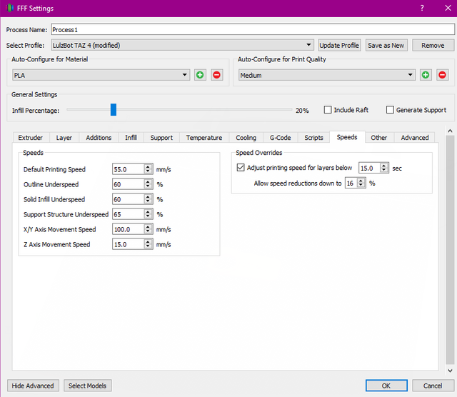
Speeds tab:
Everything is pretty self explanatory here. Print speeds can be slowed down for perimeters and external solid layers to improve finish quality, and slower speeds are necessary for printing thinner layers. Additionally, the speed can be reduced for layers that are small and would otherwise be completed before they’ve had enough time to cool. We now close the print settings window and click Prepare to Print!
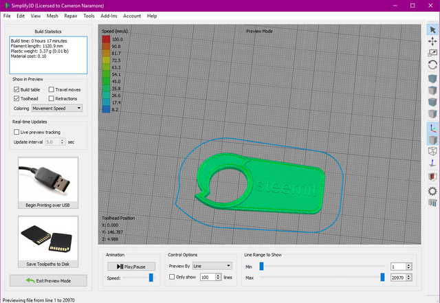
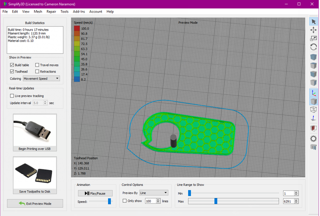
We’re presented with a preview, which looks good.
By dragging the Max Line Range to Show bar backwards, we can see the honeycomb infill. Next, we click Save Toolpath to Disk, which creates a steemit.gcode file. That file is transferred to an sD card and then inserted into the printer.
Printing
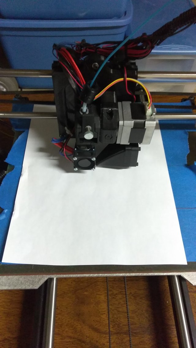
The first step is to apply some blue painters tape because it has good adhesion and removal properties. Next we heat the bed to our printing temp. Then we check bed levelness by:
1. homing the toolhead (the extruder/hotend) via the printer controls
2. disengaging the motors via printer controls
3. inserting a regular piece of paper in between the nozzle and the bed
4. manually moving the nozzle around the bed while also sliding the paper around to gauge the resistance; the paper shouldn’t freely move, but it should be easy to move.
5. adjust the corners of the bed accordingly so the paper slides under the nozzle with little effort at every point of the bed
Finally, we initiate the print.
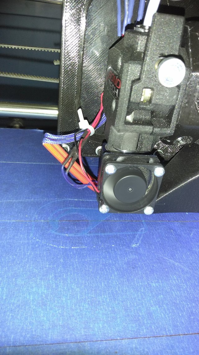
Here you can see and hear it printing the infill.
Click for video
17 minutes later, we have a keychain that is easily popped off with a paint scraper or spatula.
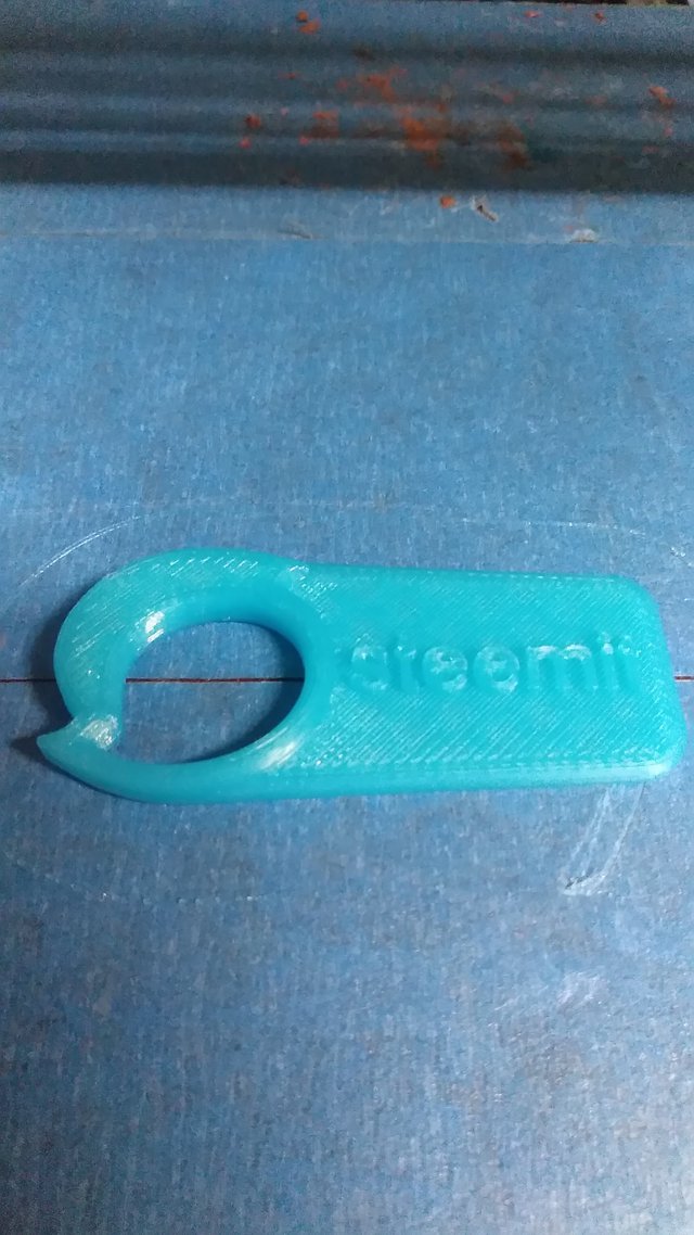
And that’s all there is to it. I hope this fills in some blanks for some future makers out there. This is my first tutorial, so sorry if there are too few/many pictures/words. I know the logo isn’t an exact match, but I didn't want to make the post longer by explaining screen ghosting software. Maybe I’ll learn some basic video editing to make more complex modeling tutorials if there’s interest. So please upvote, follow, and comment for more content.
Please, I would love to see more of this. More samples.
Ths is amazing !