Electrical Transformer

Thomas A. Edison was able to build power station over New York in 1882. It was the first time were electricity is publicly available in a community. Edison’s power station delivers 120 V dc which primarily able to lit incandescent bulbs. Unfortunately, his power station is unable to supply significant amount of power. These high current caused huge voltage drops and power losses in the transmission lines, severely restricting the service are of a generating station. In 1880s, central power station was located every few city blocks to overcome the problem. In fact, lesser power transmitted for far distances with low-voltage dc power system means generating stations had to be in every block and be localized. So, this was relatively costly and inefficient.
The development of transformer together with the persistent growth of ac power sources eliminated this restrictions. A transformer ideally changes one voltage level to another voltage level, either steeping up or down the supply. If the transformer steps up the voltage level in the circuit, it must relatively decrease the current to keep the power the same. Therefore, power can now be generated from one electric power station which is transmitting a stepped up voltage over long distances at a very low losses. Wherein, the voltage transmitted can be stepped down when utilize in our homes.
Since transmission losses in the line s of a power system, raising the transmission voltage and reducing the currents result to a more efficient means of transmitting power at a minimal loss and cost. Without transformers, it would simply not possible to use electric power in many ways it is used today, including remote areas. The development has pave humanity to greater highs of innovation and developments.

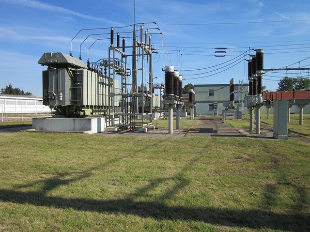
In modern power system, electric power is generated voltages at 12 to 25 kV. Transformer step up the voltage to between 110 kV and nearly 1000 kV for transmission over long distances. Transformers step down the voltage to 12to 34.5 kV range for our local utility to distribute to the consumers. Finally, further step down the voltage to permit a safe use in homes, offices, and factories as low as 120 V or 230 V.
Typically, transformer is used to convert ac power at one voltage level to a power at another voltage level, regardless of steeping up or down. Aside from that, transformers are used for voltage sampling, current sampling , and impedance transformation.

Power transformers are constructed either core or shell type. Transformers that are constructed with simple rectangular laminated piece of steel with the transformer winding is wrap around is known as core form. On the other hand, a transformer with three-legged laminated core with the winding wrapped around the center leg is called shell form. In either case, the core is constructed of thin lamination which are electrically isolated from each other to minimize eddy currents.
The primary and secondary winding s in a physical transformer are wrapped one on top of the other with the low voltage winding innermost.By doing such arrangements, we can be able to:
- simplifies the means of insulating high-voltage winding on the core; and,
- lesser flux leakage as compared with those winding are separated.

Furthermore, a special type of transformer are used primarily for measuring the voltage and current in electric machinery and power system. One of these transformers are specially designed to sample a high voltage and produce a low secondary voltage which can be sense by our meters. This is called a potential transformer. Regular power transformer can be able to step down a high primary voltage to a directly proportional voltage. The difference between a potential transformer and power transformer is that potential transformer is designed to handle a very low amount of current. In addition, the second special type of transformer is a current transformer. This is designed to provide a very small amount of current but proportional to the primary current. Typically, the voltage transformation ratio for this transformer are 10:1 and 5:1.
Transformers operates by means of a shared magnetic field across both its winding. Once the primary winding has a current flowing through it, it induces a magnetic field relative to the magnitude of the current. The phenomenon is called self-induction. Self-induction follows the electromagnetic induction principles as stated by Faraday. Over time, the greater amount of current flowing trough the primary winding the more strength is gained by the magnetic field it has induced. In this manner, causing a linkage of magnetic flux with the secondary winding. The changing magnetic flux experienced by the secondary winding triggers a static induction of voltage across the terminals of secondary winding of a transformer. The cause of inducing voltage at the secondary winding of a transformer is due to shared magnetism along the core by means of mutual induction.
An ideal transformer is a lossless device wherein the voltage transformation takes place as a ratio between the number of turns of the primary winding over the secondary winding. This could also be attain by dividing the rated voltage at the primary and the secondary. So, the voltage ratio defines the ability of the transformer to transform the voltage into a certain level, either stepping up or down. Also, it affect the magnitude of the voltage across the transformer but not the power factors.
Reference:
- Chapman, Stephen J. (2012). Electric machinery fundamentals. New York :McGraw-Hill
- Theraja, B., & Theraja, A. (2002). A Textbook of electrical technology: Basic electrical engineering in S.I. system of units (23rd ed.). NewDelhi: S. Chand.
- Siskind, C. S. (1959). Electrical machines; direct & alternating current. New York: McGraw-Hill.
Are you incline in reading and writing STEM (Science, Technology, Engineering and Mathematics) related posts? You should consider joining the #steemSTEM community on Discord here and chat with us.
Posted from my blog with SteemPress : https://engrjueco.000webhostapp.com/2018/07/electrical-transformer-2
https://steemit.com/meme/@krrrr13/should-twitter-ban-donald-trump
Congratulations! This post has been upvoted from the communal account, @minnowsupport, by juecoree from the Minnow Support Project. It's a witness project run by aggroed, ausbitbank, teamsteem, theprophet0, someguy123, neoxian, followbtcnews, and netuoso. The goal is to help Steemit grow by supporting Minnows. Please find us at the Peace, Abundance, and Liberty Network (PALnet) Discord Channel. It's a completely public and open space to all members of the Steemit community who voluntarily choose to be there.
If you would like to delegate to the Minnow Support Project you can do so by clicking on the following links: 50SP, 100SP, 250SP, 500SP, 1000SP, 5000SP.
Be sure to leave at least 50SP undelegated on your account.
No hotlinking bro
Hi @juecoree
U tried to explain the general principals of electrical transformers... The article is informative but i think u should add the source links of ur images individually under each image.. It would make easier for the curators to verify the source of the images..
Good day..!