Do It Yourself: "Expanding the Range of your old Ammeter"
The ammeters, we commonly buy at the electronics shop have a single range of measurement mostly. If we wish to measure a current beyond the range of our ammeter, we are forced to buy another ammeter that has a higher range which is very expensive. The goal of this project is to help the consumers lessen their expenses by extending the range of their D’Arsonval ammeter.
"When a direct current (DC) flows through the coil, the coil generates a magnetic field. This field acts against the permanent magnet. The coil twists, pushing against the spring, and moves the pointer. The hand points at a scale indicating the electric current. Careful design of the pole pieces ensures that the magnetic field is uniform, so that the angular deflection of the pointer is proportional to the current. A useful meter generally contains provision for damping the mechanical resonance of the moving coil and pointer, so that the pointer settles quickly to its position without oscillation."
Reference: https://prugalvanometer.weebly.com/operation.html
How the range of the ammeter is extended?
"The use of current dividers, often called shunts, allows a meter to be calibrated to measure larger currents. The shunt resistors allows the excessive amount of current in the circuit to be dissipated. Thus, only the allowable amount of current that falls to the range of the full scale can be read from the ammeter."
Reference:https://www.allaboutcircuits.com/textbook/direct-current/chpt-8/ammeter-design/
How to compute for the meter resistance and the shunt resistance?
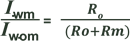
First, we measure the ammeter resistance using the accuracy formula,
And, the shunt resistors are measured using the formula,
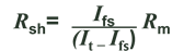
where Iwm is the current with ammeter connected in a series circuit; Iwom is the current without the ammeter connected in a series circuit, it can be directly solved using the ohm’s law; Ro is a resistor used in the series circuit that has a current flowing through that is equal or less than the full scale range of the ammeter or Ifs; It is total current in the series circuit and it is also the desired range that you want to have in extending the range of your ammeter; Rsh is the value of the shunt resistor and Rm is the meter resistance.
References: Malvino, Albert Paul. Electronic Instrumentation Fundamentals . McGraw-Hill, 1967.
Application
The use of a shunt resistor alongside an ammeter to quantify current can be a valuable way for simplifying the frequent current measurements in a circuit. Regularly, to quantify current through a circuit with an ammeter, the circuit would need to be broken or interfered as it should be connected by series.
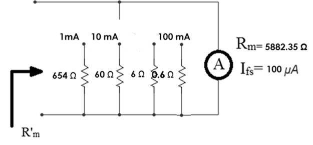
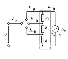
Circuit Diagram
Innovation
To make a multi-range ammeter, a selector switch can be used to connect one of a number of shunts across the meter. It must be a make-before-break switch to avoid damaging current surges through the meter movement when switching ranges.
A better arrangement is the Ayrton shunt or universal shunt, invented by William E. Ayrton, which does not require a make-before-break switch. It also avoids any inaccuracy because of contact resistance.
Since the ammeter shunt has a very low resistance, mistakenly wiring the ammeter in parallel with a voltage source will cause a short circuit, at best blowing a fuse, possibly damaging the instrument and wiring, and exposing an observer to injury.
Deduction of the Possible Causes of Errors in the Current Measurement
The most crucial part in the making of this project are the calibration stage and the testing test, wherein we need to calibrate the accuracy of our ammeter to 95 % to a 100% if possible. The calibration stage was already done in the previous stage of our project, where we match the shunt resistance of each of our current ranges to the computed value as much as possible using the accuracy formula. And as expected, the measured value of the shunt resistors, which is close to the actual value, is just approximately equal to the computed value. The exact value is quite impossible in real life, especially when dealing with discrete components. The calibration stage involved measurements of currents inside the range of each of our ranges that has to be closer to the actual value. In our first attempt to measure a current that is above the original range of our ammeter which is 100 μA, we have reached an accuracy of 94 % in the supervision of our instructor. Still, it wasn’t enough to meet the benchmark.
So, we have to think of what factors affects the accuracy of our ammeter. And then, I realized that there are factors outside the circuitry of my ammeter, and these are the tolerance of my resistors used in the circuit. The labeled-value of the resistors used in the measurement of current in my test circuit, will never be equal to its actual value. So, I decided to use the measured value of the resistors instead of their value in the computation of the current that is to be compared with the full scale reading of the ammeter. Another factor, as well, is the voltage used. The voltage may not be precisely equal to the value you desired to have, especially when you are using a battery which voltage is not precisely equal to its labeled value. Maybe near to it but it is not 100 % equal. Thus, it can be a cause of error in the current measurement, when you are already comparing the full scale reading to the computed value of the measured voltage to the measured resistance. Instead of battery, we have decided to use a power supply as a voltage source.
Testing Stage
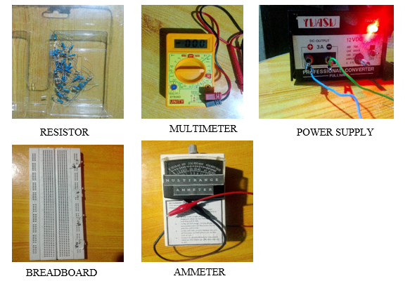
The testing stage of this project is the judgment stage of our project, as well. This is the time when we really have to achieve the benchmark for accuracy by considering all the factors that may have affect the accuracy of our ammeter. To start with the testing stage, the following are the materials that we will be using:
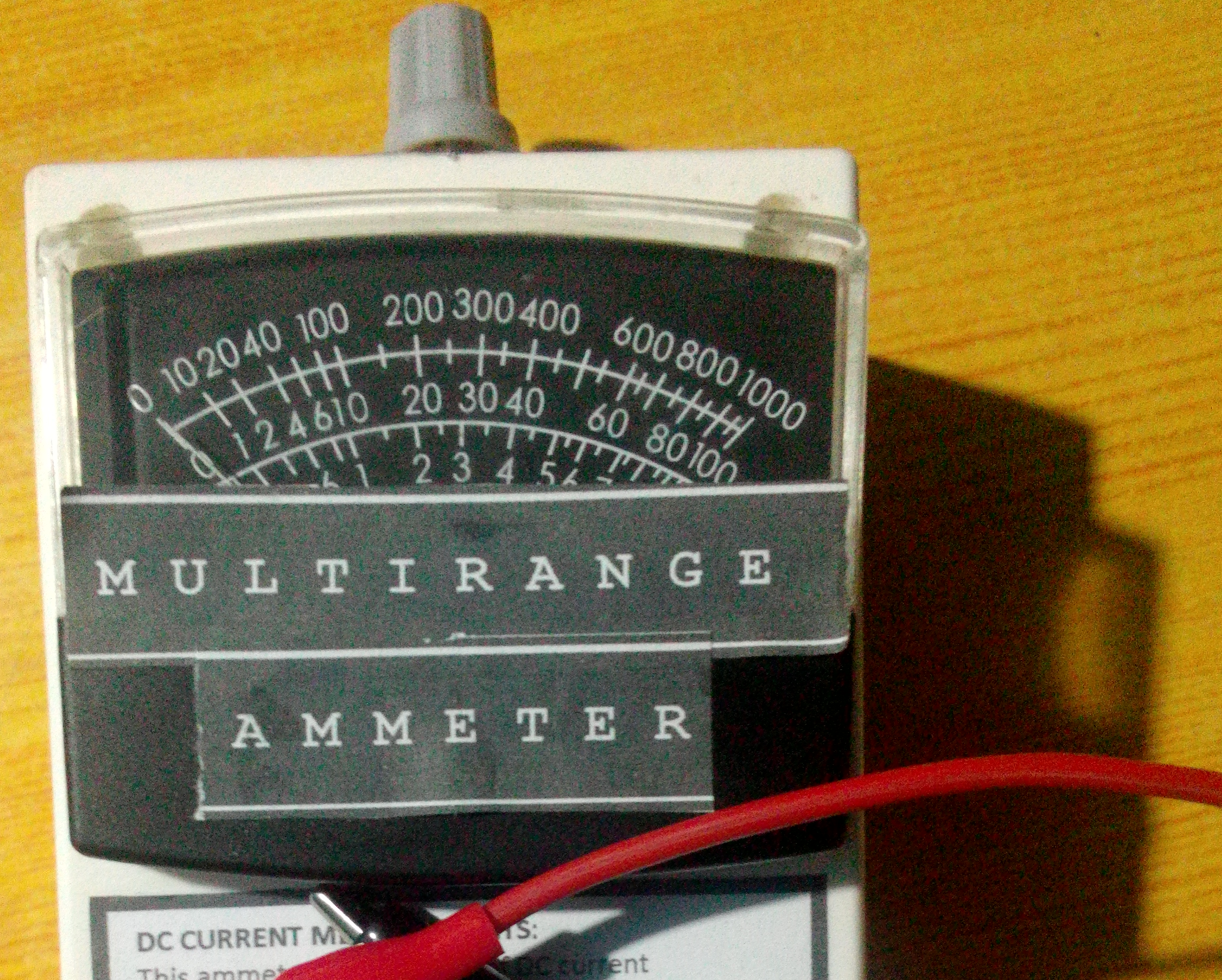
This multirange ammeter has 4 ranges: 1mA, 10 mA, 100 mA and the 1 A. But due to safety precautions, we chose not to try the 1A range.
Procedures and Data
In gathering the data for this project, I made an observation on the current ranges in 10%, 50% and 100% of each of the new ranges of 1 mA, 10 mA and 100 mA. It requires a significant amount of data in each of ranges to assure that this project is functional. Testing for accuracy for this project is really important since this project can be used for instrumention purposes.
For the 1 mA range
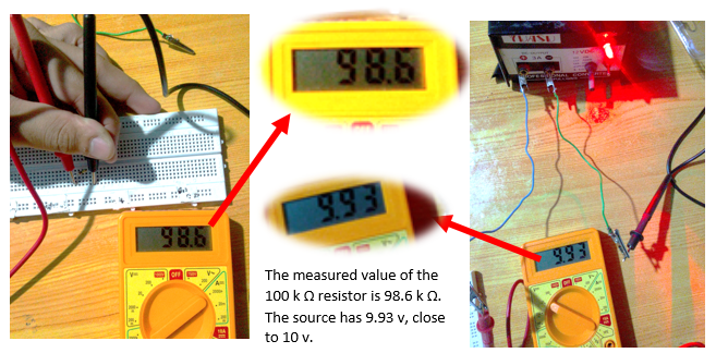
We started measuring on the 1 mA range. NOTE: The 100 μA is the original full scale range of the ammeter. There are no shunts connected across it in our circuit. We wished to measure a current of approximately equal to 0.1 mA, a value close to zero in this range. To do it, first, we measured the resistance of the resistor of a labeled value of 100 kΩ and a source of 10 v from the power supply.
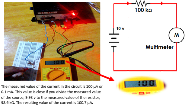
To have a comparison on the current in the testing circuit, we decided to measure the current using both the multimeter and the ammeter. First, we measure it using the multimeter. The circuit diagram and the figure are shown below.
After, we will measure the current using the same circuit, as shown in procedure no. 2, using our ammeter.

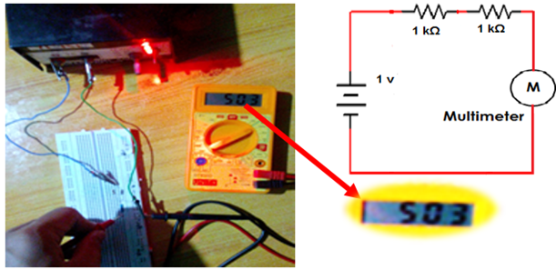
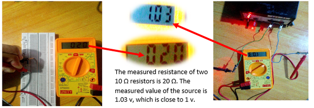
Now, we will measure at the mid-scale value. We wished to measure a current of 0.5 mA. Like what we did in the beginning of the testing stage, we measured the value of the resistor to be used and the source. We will use two 1 kΩ resistors and a 1 v power supply to have a computed value of 0.5 mA.
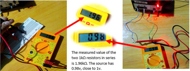
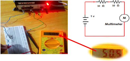
To have a comparison on the current in the testing circuit, we decided to measure the current using both the multimeter and the ammeter. First, we measure it using the multimeter. The circuit diagram and the figure are shown below.
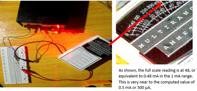
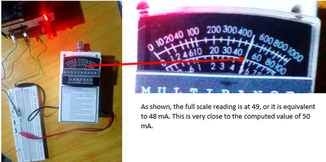
After, we will measure the current using the same circuit, as shown in no. 5, using our ammeter.
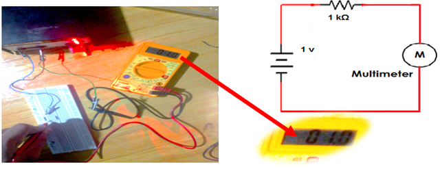
Now, we will measure at the maximum scale value. We wished to measure a current of 1 mA. Like what we did in the beginning of the testing stage, we measured the value of the resistor to be used and the source. We will use a 1 kΩ resistors and a 1 v power supply to have a computed value of 1 mA.
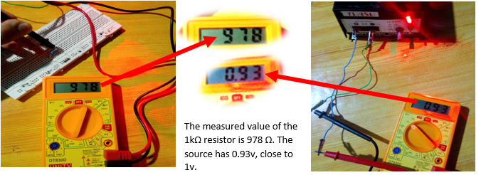
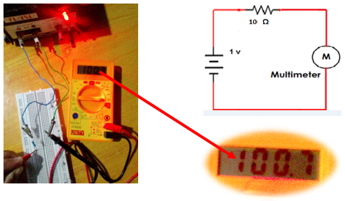
To have a comparison on the current in the testing circuit, we decided to measure the current using both the multimeter and the ammeter. First, we measure it using the multimeter. The circuit diagram and the figure are shown below.
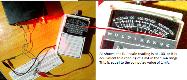
After, we will measure the current using the same circuit, as shown in no. 8, using our ammeter.
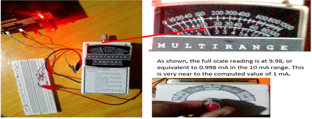
For the 10 mA range: 1. We wished to measure a current of approximately equal to 1 mA, a value close to zero in this range. Like what we did in the beginning of the testing stage, we measured the value of the resistor to be used and the source. We will use a 1 kΩ resistors and a 1 v power supply to have a computed value of 1 mA.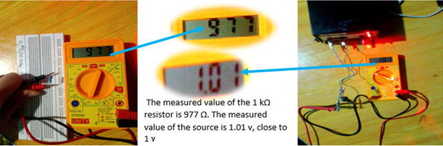

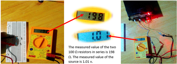
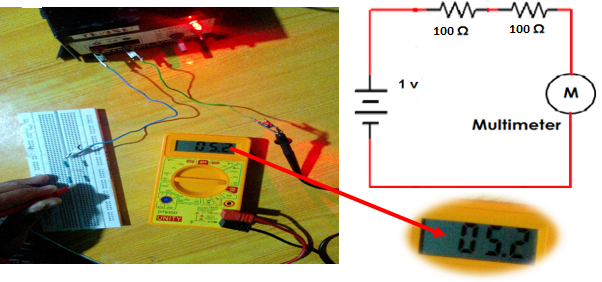
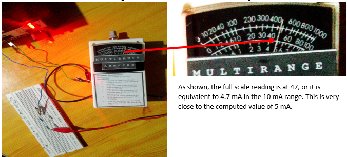
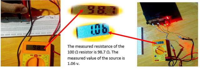
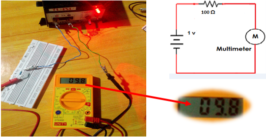
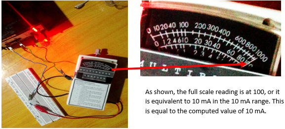
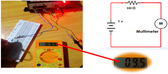
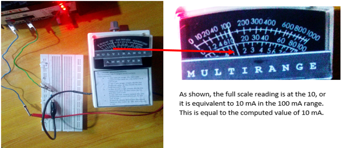
For the 100 mA range: 1. We wished to measure a current of approximately equal to 10 mA. Like what we did in the beginning of the testing stage, we measured the value of the resistor to be used and the source. We will use a 100 Ω resistor and a 1 v power supply to have a computed value of 10 mA.


Generalization:
Based on the results, this multi-range ammeter has an accuracy ranging from 96-100 %. Thus, when the factors affecting the accuracy is identified, the accuracy of the ammeter becomes higher because you considered these factors. By compensating with losses and over-resistance of the resistors used through matching source to these, the actual value of current will be achieved.Recommendation:
In this project, it would be ideal to use wire stubs with similar resistances as indicated. Wire stubs as shunt resistors is very rare and available in my country so I just used some high-power rated resistors as a replacement. It will make the project more accurate in terms of current reading and it could increase the lifespan of the multi-range ammeter. Also, handling curents above 1 mA is very detrimental to some discrete components. So, always be careful.
All images used belong to @japh
So, that is all for today! If you want to replicate this project, feel free to comment and maybe I could help.
Join our Discord Channel to connect with us and nominate your own or somebody else's posts in our review channel.
Help us to reward you for making it ! Join our voting trail or delegate steem power to the community account.
Your post is also presented on the community website www.steemmakers.com where you can find other selected content.
If you like our work, please consider upvoting this comment to support the growth of our community. Thank you.
Congratulations! This post has been upvoted from the communal account, @minnowsupport, by Japh from the Minnow Support Project. It's a witness project run by aggroed, ausbitbank, teamsteem, theprophet0, someguy123, neoxian, followbtcnews, and netuoso. The goal is to help Steemit grow by supporting Minnows. Please find us at the Peace, Abundance, and Liberty Network (PALnet) Discord Channel. It's a completely public and open space to all members of the Steemit community who voluntarily choose to be there.
If you would like to delegate to the Minnow Support Project you can do so by clicking on the following links: 50SP, 100SP, 250SP, 500SP, 1000SP, 5000SP.
Be sure to leave at least 50SP undelegated on your account.