Teardown/Explanation of an Electric Fly-Swatter
I've decided to do two teardowns in a row because I got the tools to disassemble the radio on the same day that I picked up this cheap device. This will be a quicker post (I think).
You've probably seen electric flyswatters. If a fly or mosquito flies in one, they are instantly killed or stunned by a pulse of electric current. I had a lot of fun using one when I visited Alaska several years ago, but thankfully my current university has pretty much no problematic insects. However after seeing this at a local store I decided I wanted to grab it and see what's inside. I was personally hoping for a power supply capable of a few thousand volts to charge up the swatter that I could use for something else (another thing to add to the list of things to do after this busy quarter is over...)
What does an electric flyswatter do?
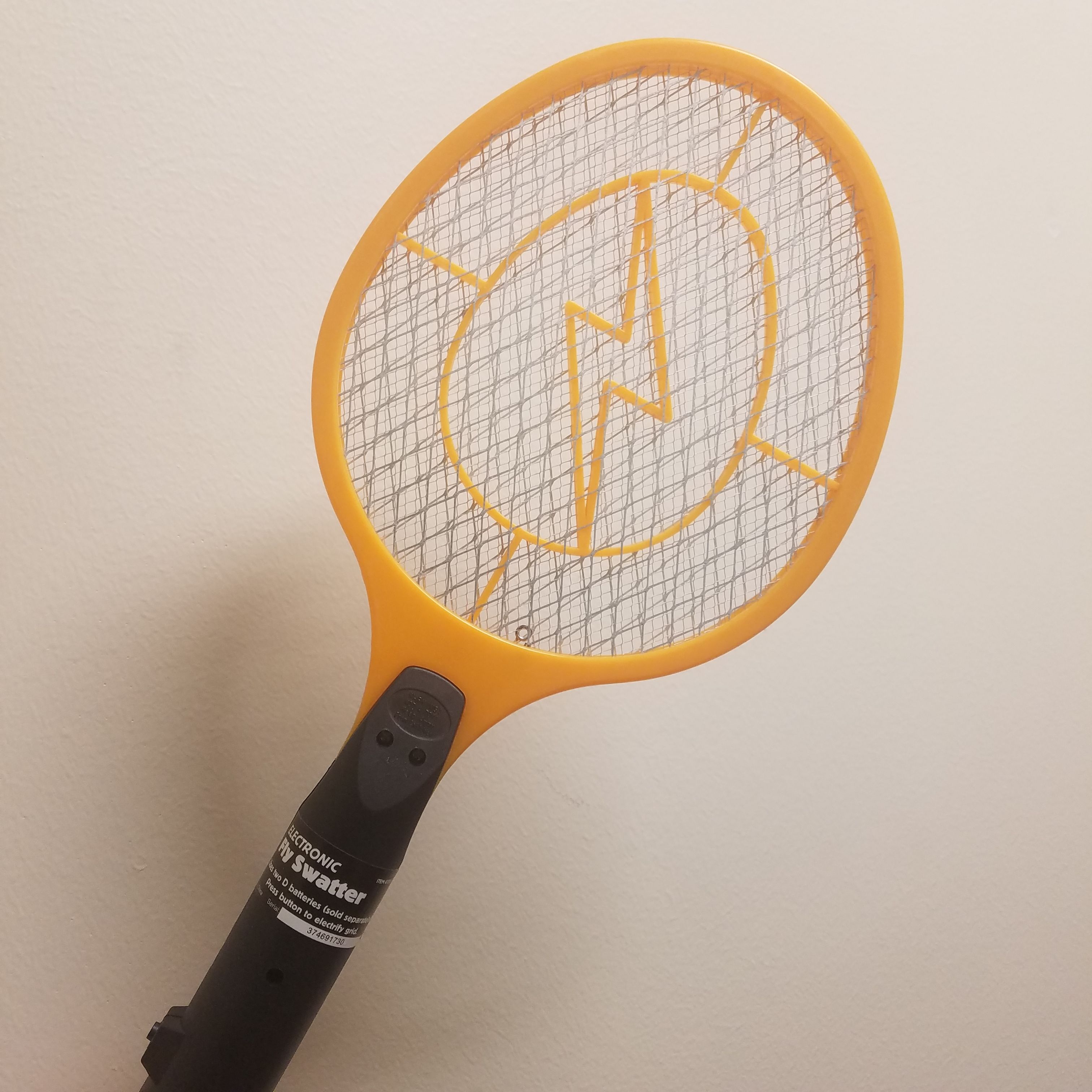
Load two D-cell batteries into this oversized metal tennis racket and you can press a button to light up a red LED and charge the metal grids. The top of the racket contains three parallel grids. The outer two are grounded to the negative terminal of the batteries. The center one is set to a high potential by the internal circuitry. When you hit a mosquito with this device, the insect gets trapped between the grids. If the mosquito touches the inner grid and the outer grid at once, a huge (for the mosquito) pulse of energy gets fired through its body, killing or stunning it.
It's really that simple. Grounding the outer grids makes it difficult to accidentally shock yourself while spelling certain doom for any insect unfortunate enough to find itself approached by this racket. And from personal experience, these devices are quite useful if you live in a mosquito-infested area and want to kill the ones that got into your house in electric style (although a good net is going to be more effective in general).
Let's look inside.
Teardown
The device is just a big plastic and metal tennis racket, essentially. The three metal grids are clearly visible.
It's actually very easy to take apart. There are four screws on the back that let the black plastic handle split in half. This reveals a very large battery compartment (they probably should have used C or AA cells for this) and a small circuit board:
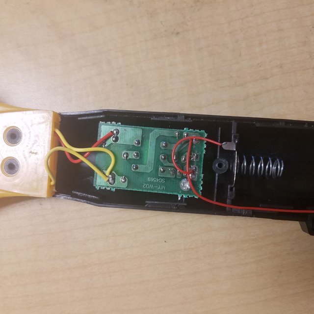
You can see three wires going to the grids (red for high voltage, yellow for harmless battery ground). A single screw can be removed to pull the PCB off of the frame:
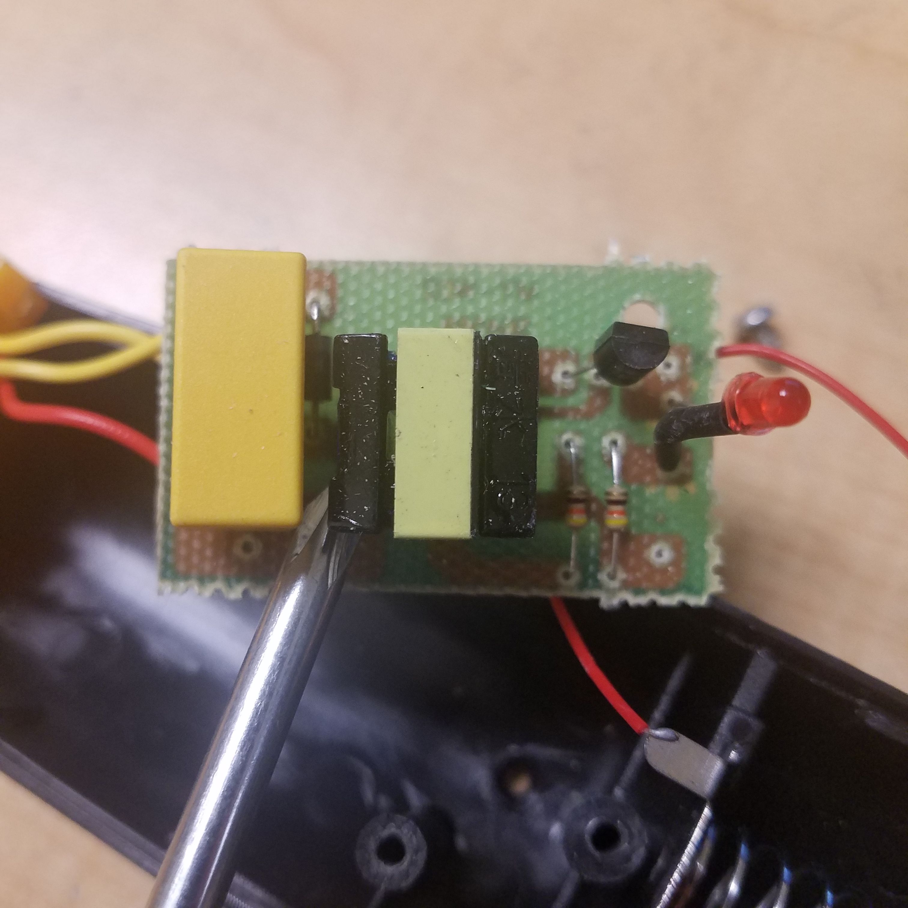
Visible is a big yellow capacitor, a transformer, a transistor, a couple resistors, and a red LED. Not visible is the push button that turns on the circuit.
Press the button and the LED lights up. The grid also charges up to a high voltage by charging the yellow capacitor, which stores energy until an unfortunate fly comes along to discharge it. The transformer assists in boosting the voltage, since a capacitor charged to 3 volts from the batteries isn't going to harm anything.
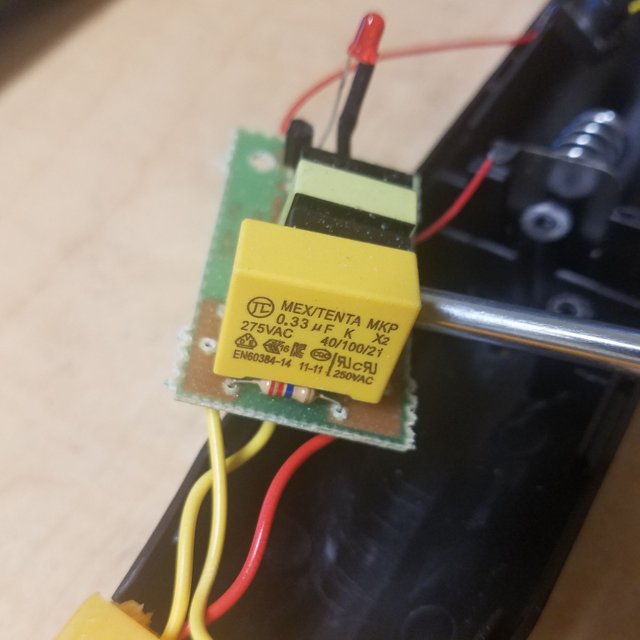
Here you can see a discharge resistor across the capacitor. This high value resistor drains the capacitor when not in use, to prevent it from accidentally shocking someone. Holding the button continuously will keep the capacitor charged and ready to kill mosquitoes.
How this circuit works
The circuit is pretty straightforward, so I drew a full schematic. I tried to be as accurate as possible, but there are likely some small errors due to my inability to see the inside of the coil.
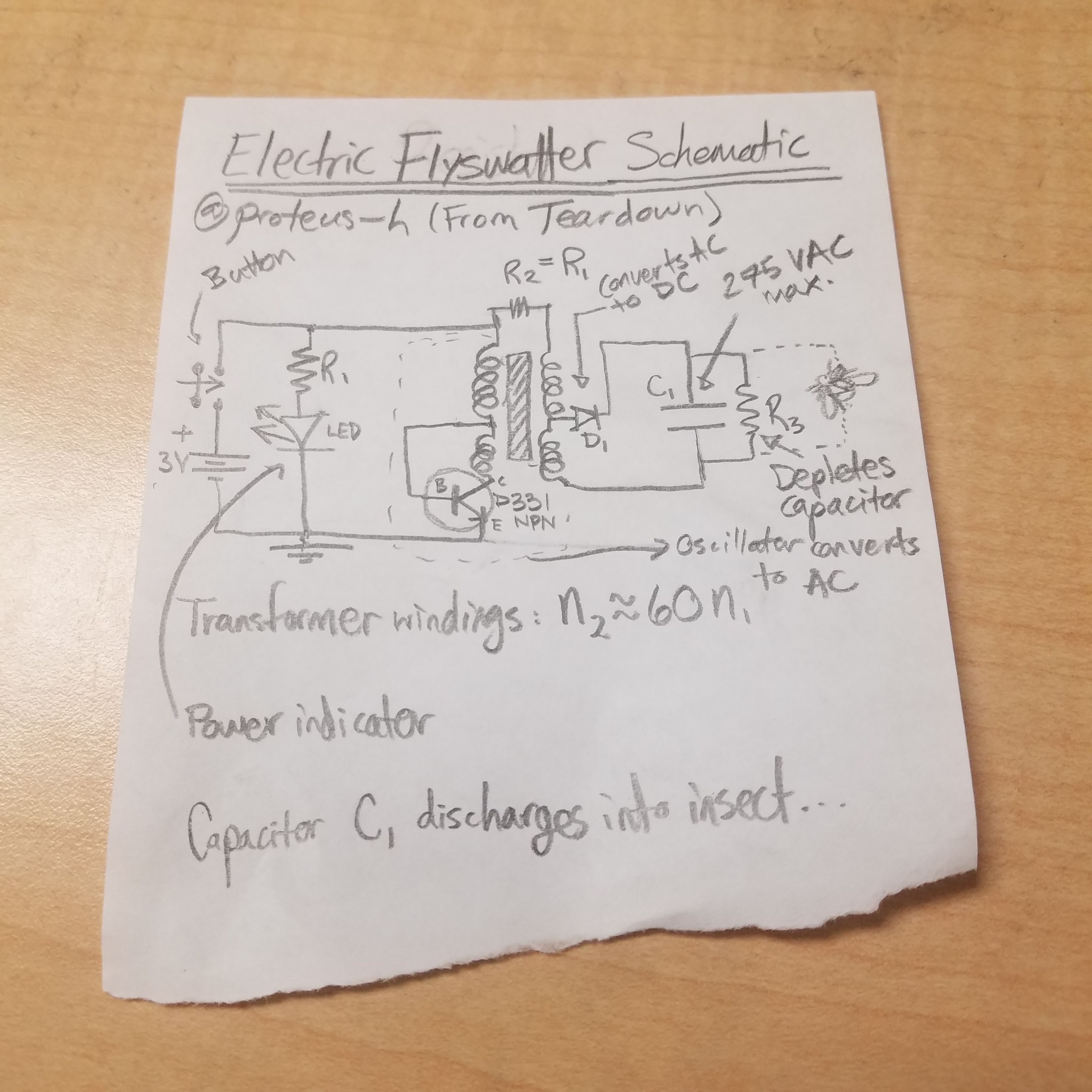
As you can see, pressing the button brings the entire top rail to +3 volts. This causes current to flow through the resistor and LED, lighting the LED and letting you know that the circuit is on. Note that this means if you rip out the LED, it won't affect the actual flyswatter circuit.
Take a look at the left side of the transformer. When you turn on the device, the top of the coil is at 3 volts. This causes current to the flow through the inductor. Current can't flow across the transistor yet, since E and C are disconnected. Once the first coil has settled down and the current comes to steady flow, the voltage at the base of the NPN transistor (a D331 NPN transistor by the label) will be high enough to "turn on" the transistor. This opens the gates between the collector (C) and emitter (E) pins.
With the transistor "on", current flows through the second coil (bottom left) through the transistor to ground. Since this coil is an inductor, it produces a rapidly rising magnetic field around it as the current increases. This induces a current in the upper coil, which causes the inductor to produce a voltage difference across it, reducing the voltage of the base relative to the emitter. This should turn off the transistor, shutting down the second coil, and the whole process repeats again. The effect is that a single transistor and these coils has produced an oscillator, and has converted DC from the batteries into low-voltage AC (alternating current). Note that this is my best guess to what is happening, and the exact specifics may be different based on the structure of the hidden transformer coils - please feel free to let me know if this wrong.
What this transistor then does is induce an oscillating current in the transformer coils on the left side. The right side of the transformer (the output) has way more turns of wires than the input (about 60 times more in this case), causing the voltage on the output of the transformer to be an AC signal with much higher voltage and much lower current. The result is that the circuit has produced a 200 or so volt alternating current on the output of the transformer from a low voltage input.
But notice that there is a diode on the output of the transformer. This diode only lets current flow through it in one direction, so the diode effectively rectifies the output, producing pulsed direct current. This direct current can then charge up the capacitor to ~200 volts, letting it kill some mosquitoes when they touch the racket's grids.
There's also a big resistor across the capacitor. This slowly discharges the capacitor when the circuit is turned off, so that if you store the racket and then touch the grids an hour later you don't shock yourself.
That went a little longer than I expected. Please let me know if you have any questions or comments. Also, if my interpretation of the oscillator part of the circuit is incorrect, please let me know, as it's tough for me to know 100% what is happening without seeing inside the transformer.
Thanks for reading!
All images used in this post are my own. You are welcome to use them with credit.
Being A SteemStem Member
By the way, this is also an excellent article in this respect https://gadgets-reviews.com/review/714-best-electric-fly-swatters.html I really liked it. There are a lot of practical things painted, so I recommend reading it to you too.
I'm wondering how much of a shock a fully charged 275V 0.33 uF Capacitor would give you? (Please don't try it...lol!)
Such a capacitor would store 0.5 * (.33e-6 F) * (275 V)^2 = 1.25 Joules. Suffice to say it would probably hurt, as it's about 2% of the energy in the sometimes deadly microwave oven capacitors.
As someone who accidentally touched one, I can say it hurts like hell but doesn't do any lasting damage.
Hurting without causing lasting damage? Sounds like the kind of thing the CIA would be interested in.
Um, no!
I either didn't know such a thing existed, or I forgot that I knew!
It looks quite useful!
i have one of those once for 2EUR or so. really usefull! i measured the grid voltage once, but my fluke multimeter maxed out at 1000V DC (!!!) so its really beefy. if you dont care about safety, you could even cut out that discharge resistor at the capasitor. keeps the voltage up even more. you might want to replace the low-end low voltage capacitor with a real high voltage one. the bigger the better. then this beast really vaporizes whatever it touches.
You've got the schematic all wrong, the secondary coil isn't center tapped and not connected to the feedback coil with R2...
Saya suka informasi kamu.terimakasih sudah berbagi.☺
Mf saya kurang bisa bahasa inggris.
Saya upvote kamu.
Nice post, such an information