Fleming's rules and its applications in electric motor and electric generator
In 19th century, John Ambrose Fleming originated both Fleming’s left-hand rule and Fleming’s right-hand rule as a means of getting motion direction in an electric motor and electric current direction in an electric generator.
If a conductor carrying current is positioned in a magnetic field, a force is being experienced as a result of the magnetic field. Conversely, if a conductor in a magnetic field moved, an induced emf spread across the conductor.
Two rules are involved in the determination of direction of motion in electric motor and induced current direction determination in electric generator. The rules are Fleming’s left-hand rule for motor and Fleming’s right hand rule for generator respectively.
Fleming’s left hand rule
Whenever a conductor carrying current is being placed inside a magnetic field, a force in a direction perpendicular to both the directions of magnetic field and current acts on the conductor. In this rule, a part of a conductor with the length L is put vertically in a horizontally placed magnetic field strength H, Produced by N and S of the magnet. If the current flowing through the conductor is I, then the size of the force that is acting on the conductor is,
F= BiL

By Douglas Morrison DougM - en.wiki, CC BY-SA 3.0,Fleming's left-hand rule
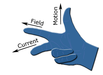
According to Fleming’s left hand rule, if forefinger, second finger and thumb are stretched perpendicular to each other and forefinger denotes the direction of field, the second finger represents current and the thumb denotes the direction of the force.
One magnetic field is induced around a conductor when current flows through it. By considering the numbers of closed magnetic lines of force that surround the conductor, the magnetic field can be imagined. Through Maxwell’s corkscrew rule or right-hand grip rule, the direction of magnetic lines of force can be determined. The direction of the lines of force (flux lines) is clockwise as this rule is concerned if from the viewer the current is flowing away, as in through the conductor, the direction of the current is inward from the reference plane.
If the magnetic field is applied horizontally to the conductor externally, the field around the conductor as a result of current passed through it and field applied externally are the two magnetic fields that usually interact with each other. It can be noticed that magnetic line of force of external magnetic are from N to S pole.
The magnetic lines of force as a result of current in the conductor and magnetics lines of force of external magnetic field are in the same direction at the top of the conductor, and below the conductor they are in opposite direction.
Therefore, number of co-directional magnetic lines of force above the conductor will be larger than the ones below the conductor. As a result of this, in the small space above the conductor, there will exist a larger concentration of magnetic lines of force. Magnetic lines of force are under tension like stretched rubber band as they are no longer straight line.
Due to this, a force will exist that will want to move the conductor to a less concentrated magnetic field from more concentrated magnetic field, that is from upward position to downward position. It can now be observed from above explanation that the directions of current, force and magnetic field are according to Fleming’s left-hand rule.
Application of Fleming’s Left-hand rule
This rule is applicable in electric motor. So, we are going to talk about electric motor here
Electric Motor
A torque acts on the coil which rotates it continuously when a rectangular coil is positioned in a magnetic field. The attached shaft rotates when the coil rotates and thus the electric motor is able to do mechanical work.
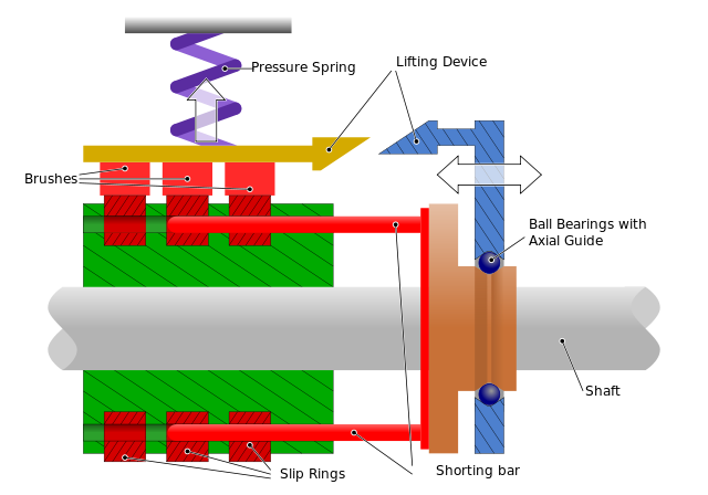
By Bürstenabhebevorrichtung.svg: Biezlderivative work: Theanphibian (talk) - Bürstenabhebevorrichtung.svg, CC BY-SA 3.0,Electric motor
Parts of an electric motor
Armature
An insulated copper wire wounded on a soft iron core in a rectangular coil is referred to as a D.C motor. This coil is placed on an exile and together they are put in between the magnet’s cylinder concave poles
Commutator
The direction of current is being reversed by the use of commutator. Commutator is referred to as copper ring which is divided into two parts which are C1 and C2. The split rings are placed on the axle of the motor and are separated from each other through insulation. These rings are soldered to the two ends of the coil and rotate alongside with the coil. The rings of the commutator are connected to the battery. The wires from the battery are connected to the brushes which are in contact with the rings and not to the rings.
In summary, these brushes makes a physical contact with commutator.Therefore, in order to deliver positive and negative charge to the commutator the brushes must connect to the opposite poles of the power source.
By Abnormaal - Own work, CC BY-SA 3.0,Electric motor
Brushes
These are referred to as small stripes of carbon which is presses against two split rings slightly and between the brushes the split rings rotate. These brushes made of carbon are connected to D.C. source.
How D.C. motor works
A magnetic field is generated around the armature when the coil is powered. From the left magnet, the left side of the armature is pushed away and pushed towards the right side of the armature which results into rotationThe brushes lose contact with the commutator when the coil turns through 90 degree and the current through the coil stops flowing.
However due to the momentum of the coil, the coil keeps turning.The sides of the coil get interchanged when it rotates through 180 degree. Due to this, brush B2 is now in contact with commutator C1 and brush B1 is in contact with commutator C2. Therefore, there is continuous flow of current in the same direction
How to increase the efficiency of a D.C.motor
Increase the number of turns in the coil
Increase the flowing current strength
Increase the coil’s area of cross section
Fleming that’s right-hand rule
An e.m.f (and hence current) is induced in a straight conductor (wire) that moves at an angle in a magnetic field. Fleming’s right-hand rule determines the direction of the induced current. However, no e.m.f (and hence current) is induced if the direction of movement is parallel to the direction of magnetic field.
.png)
By Douglas Morrison DougM - en.wiki, CC BY-SA 3.0,Right-hand rule
The rule states that both the direction of magnetic field from North Pole to South Pole and the direction of motion is perpendicular to the direction of the induced current
Application of Fleming’s right-hand rule
Fleming’s right-hand rule is applicable in electric generator. Below, I am going to talk about electric generator.
Electrical generator
A machine that converts one form of energy into another is referred to as an electrical generator. Especially, it coverts mechanical energy into electrical energy
Working Principle of a generator
Electromagnetic induction is applicable in a generator. It works based on the principle that current is induced in the coil when a wire (conductor) is moved in a magnetic field. In a magnetic field between the poles of a horse shoe type magnet, a rectangular coil is made to rotate. As the coil rotates, it passes through the lines of the magnetic force through which a current is produced in a generator. Various electrical appliances are being run by the generated current.
Construction of Electric Generator
The constituent of a simple electric generator is a rectangular coil ABCD which between the poles of N and S of a strong horse shoe type magnet can be rotated rapidly. A large number of turns of insulated copper wire make up the generator coil. Copper half ring R1 is connected to one end of the coil and copper half ring R2 is connected to the other end of the coil. The two half rings R1 and R2 touch the two copper brushes B1 and B2 respectively when the coil is rotated.
So through the commutator half rings and into the carbon brushes, the current produced in the rotating coil can be taped out. Therefore, current can be supplied into various appliances from the carbon brushes B1 and B2.
Detailed Principle of a working generator
Suppose initially the generator coil ABCD is positioned horizontally. As the coil rotates between the North and South poles of the magnet in the anticlockwise direction, the AB side of the coil moves down thereby cutting the magnetic lines of force near the magnet North pole and DC side of the coil cut the line of force near the South pole of the magnet when it moves up.
As a result of this, sides AB and DC of the coil produce induced current. It is found out that the two sides of the coil are in the same direction when Fleming’s right-hand rule is applied to the AB and DC sides of the coil and in the direction BADC an effective induced current is generated. Therefore, brush B2 becomes the negative pole and brush B1 becomes the positive pole of the generator.
The position of the sides AB and DC of the coil get interchanged after a half revolution. The side CD will come on the left hand side and starts moving downward while the side AB will come to the right hand side and starts moving upward.
The two commutator rings R1 and R2 change their contact automatically from one carbon brush to another when sides of the coil interchange their positions. As a result of this change, the current keeps flowing in the same direction. Therefore, current is being supplied by a DC generator in only one direction.
In summary, both the Fleming's left and right hand rule work hand in hand.Therefore, there is no electric motor without electric generator and vice versa. Thanks for reading
References
- http://www.excelatphysics.com/flemingrsquos-right-hand-rule.html
- https://en.wikipedia.org/wiki/Fleming%27s_left-hand_rule_for_motors
- https://www.electrical4u.com/fleming-left-hand-rule-and-fleming-right-hand-rule/
- https://scienceeasylearning.wordpress.com/2015/05/25/flemings-left-and-right-hand-rule-and-their-applications/
- https://scienceeasylearning.wordpress.com/2015/05/25/flemings-left-and-right-hand-rule-and-their-applications/
Thank you for your contribution and posting your references!
=======================================================================================
This post was upvoted and resteemed by Steemgridcoin with the aim of promoting discussions surrounding Gridcoin and science.
This service is free. You can learn more on how to help here.
Have a nice day. :)
Congratulations @sheglow! You received a personal award!
Click here to view your Board
Do not miss the last post from @steemitboard:
Congratulations @sheglow! You received a personal award!
You can view your badges on your Steem Board and compare to others on the Steem Ranking
Vote for @Steemitboard as a witness to get one more award and increased upvotes!