Circuit design using "PSIM" (Buck and Cuk type regulators)
I am a student of electronic engineering from the Simón Bolívar University of Venezuela (USB), a few quarters ago I was in the course of “Electronics of industrial acquisition and processing systems 2” In this class was assigned the task of designing a different power supply values using Buck,Cuk, regulators, to be used in some blocks of the electric vehicle, using the simulator PSIM.
Specifications:
Acquisition Stage:
• -24 V @ 200mA.
• 5 V @ 100mA (95% efficiency).
Processing Stage:
• 3.3 V @ 10mA (95% efficiency).
• 5V @ 1A.
Process:
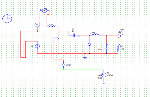
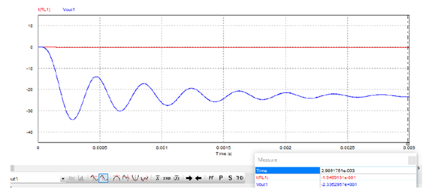
Regulator to obtain -24V @ 200mA:
The Cuk model was implemented.
For simplifications, the same value was taken for both inductors and capacitors. A switching frequency of 100 Khz was raised.
The load resistance was obtained by ohm's law, giving 120Ω.
K: 0.33.
An inductor value of 10mH was taken as reference. A 10mA and 100mV curl at the output. Obtaining a capacitor value of 201nF.
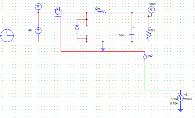
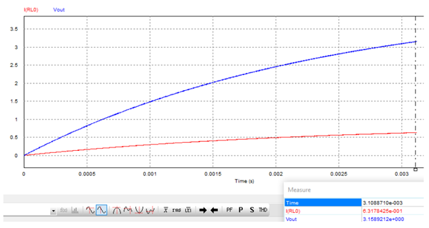
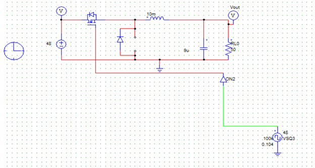
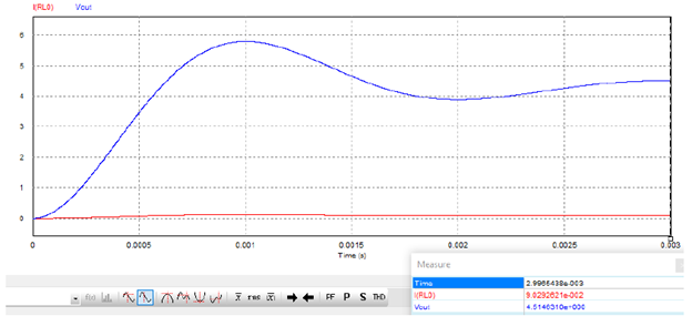
Regulator to get 5V @ 100mA:
The Buck model was implemented.
For simplifications, the same value was taken for both inductors and capacitors. A switching frequency of 100 Khz was raised.
The load resistance was obtained by ohm's law, giving 50Ω.
K: 0.104.
A 10mA and 5mV curl was taken at the output. Obtaining a capacitor value of 250nF and 12mH was obtained for the inductor. That is, an inductor less than 12mH and a capacitor greater than 250nF are required.
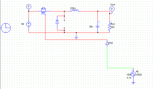
Regulator to get 3.3V @ 10mA:
The Buck model was implemented to simplify the same value for both inductors and capacitors. A switching frequency of 100 Khz was raised.
The load resistance was obtained by ohm's law, giving 330Ω.
K: 0.10.
A 1mA and 33mV curl was taken at the output. Obtaining a capacitor value of 36nF and for the inductor 120mH was obtained. That is, an inductor less than 120mH and a capacitor greater than 36nF are required.

Regulator to get 5V @ 1A
The Buck model was implemented.
For simplifications, the same value was taken for both inductors and capacitors. A switching frequency of 100 Khz was raised.
The load resistance was obtained by ohm's law, giving 5Ω.
K: 0.104.
A 10mA and 25mV curl was taken at the output. Obtaining a capacitor value of 50nF and for the inductor 12mH was obtained. That is, an inductor less than 12mH and a capacitor greater than 50nF are required.